
To ensure the effectiveness of the improvement, modeling and simulation analysis were conducted on the improved state planetary reduction mechanism.
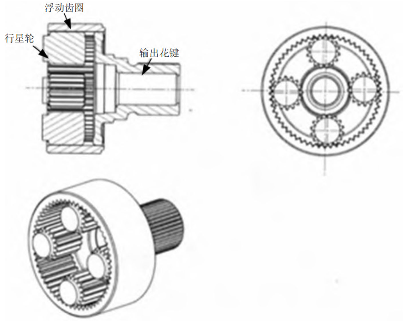
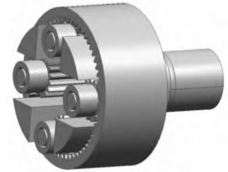
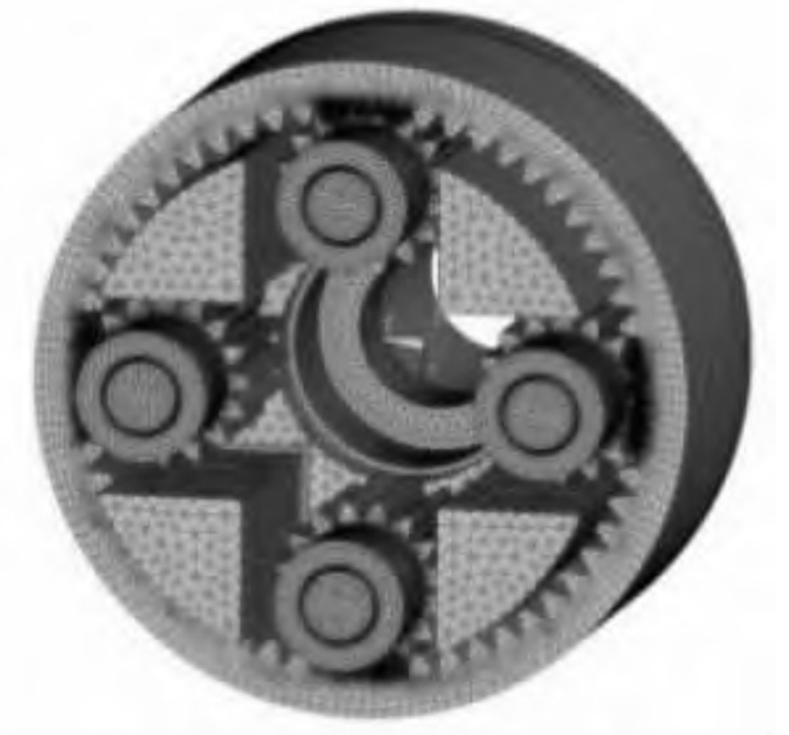
In response to the local tooth breakage of the planetary gear and floating gear ring during the fault, the planetary reduction mechanism in this section was intercepted for analysis and model establishment. The planetary reduction mechanism is composed of planetary gears, output splines, floating gear rings, planetary carriers, pin shafts, and bushings, as shown in Figure 1.
The parameterized modeling method used in the study is based on Pro/E5.0 as the development platform, using its internal integrated Program tool.
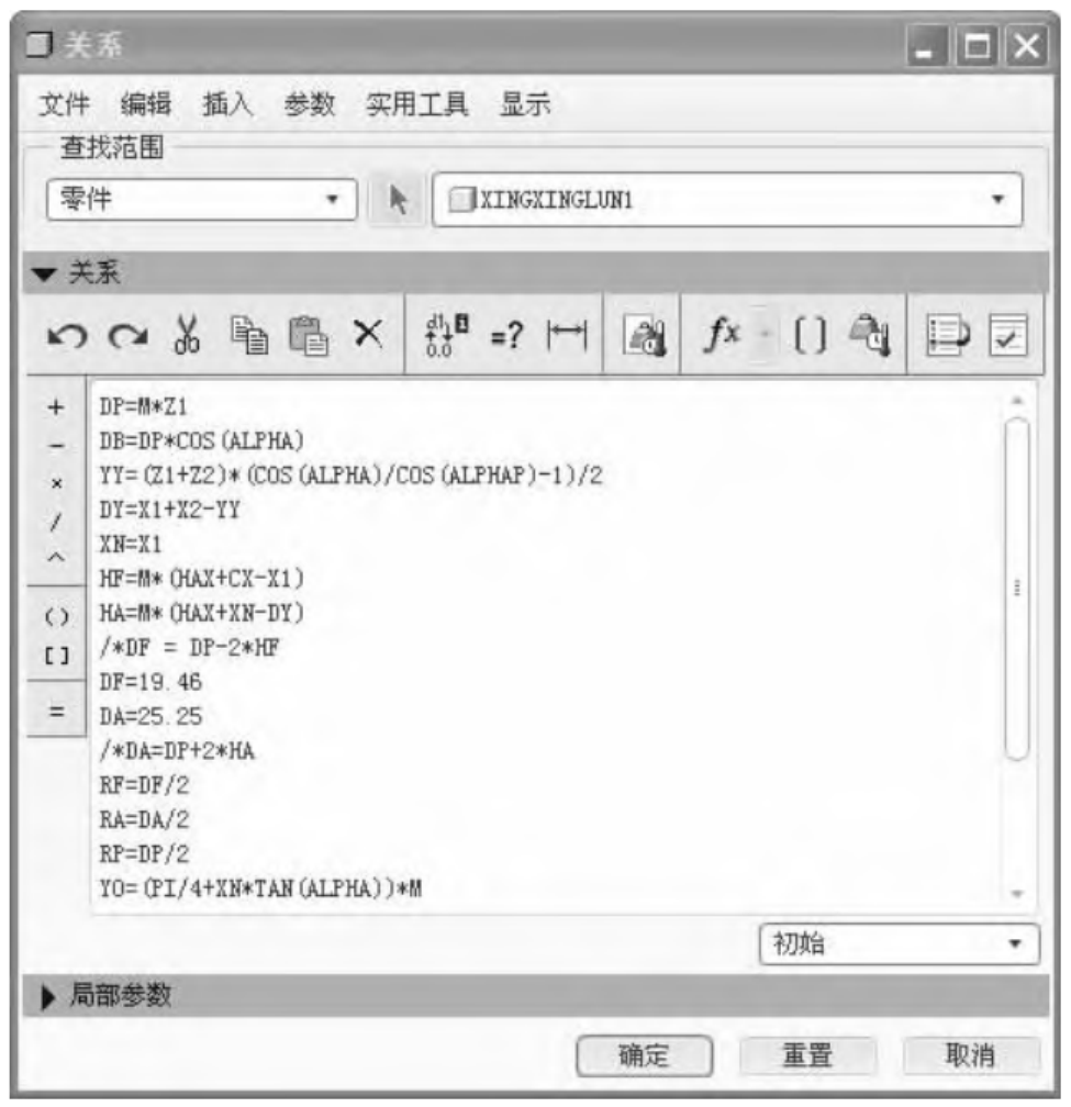
To ensure the accuracy of the analysis, the planetary gear modeling process should be consistent with the involute gear tooth profile as much as possible, and parameterization should be used for mathematical modeling. Taking planetary gear modeling as an example, enter the relevant parameters and corresponding relationship values of the planetary gear in the “Parameters” column under the “Tools” menu of the software, as shown in Figure 2.
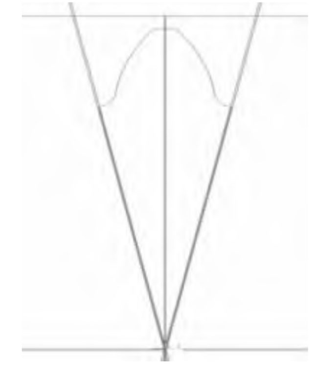
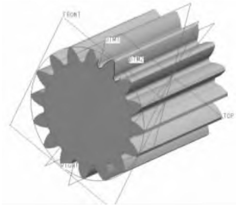
Using the above formula to draw a single external tooth profile (Figure 3), the shape of the planetary gear can be obtained after stretching, array, etc. (Figure 4).
After establishing the planetary gear model, modify and model the planetary gear, planetary carrier, output gear ring, and pin shaft according to the actual dimensions, as shown in Figure 5.
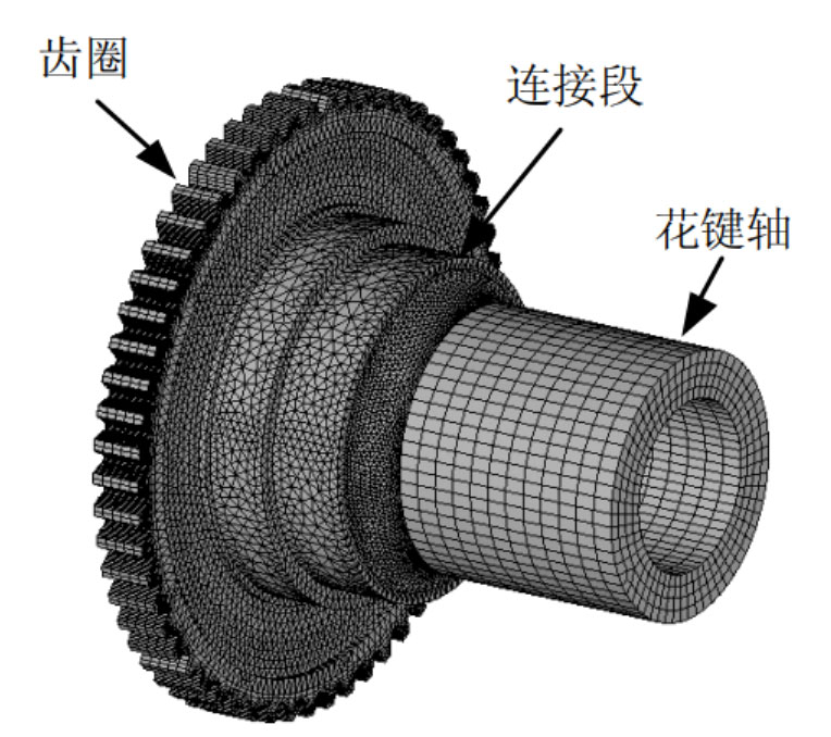
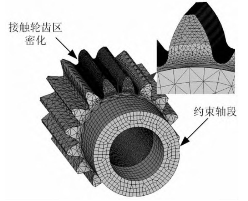
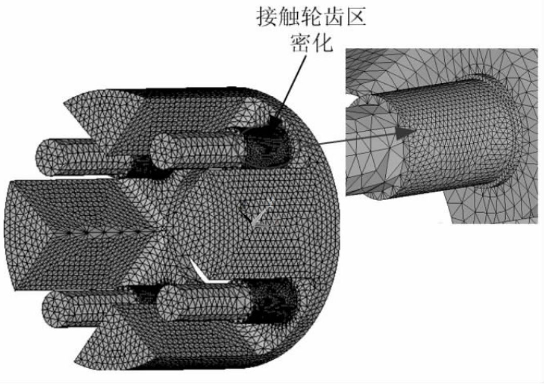
In the process of model analysis, a mixed mesh partitioning method of hexahedral and tetrahedral grids is used. For gear teeth. The parts with small changes in axial geometric structure such as wheel flanges, as well as the contact and root areas of wheel teeth, are divided into dense hexahedral grids; For connecting structures or gear teeth with chamfers, tetrahedral mesh division is used. The mesh at the contact area is relatively dense, and the mesh at the contact surface should match each other as much as possible. When dividing the mesh, the mesh density on the meshing tooth surfaces must be sufficiently high. For planetary gears and other parts that do not participate in meshing, the mesh density should be appropriately reduced to reduce computational complexity. The grid division diagram of each component is shown in Figure 6-9.

When establishing the finite element model, define the material elastic modulus E=2.1 × 10^11Pa; Poisson’s ratio: v=0.3; Obtain the output component finite element model through grid partitioning, as shown in Figure 10.
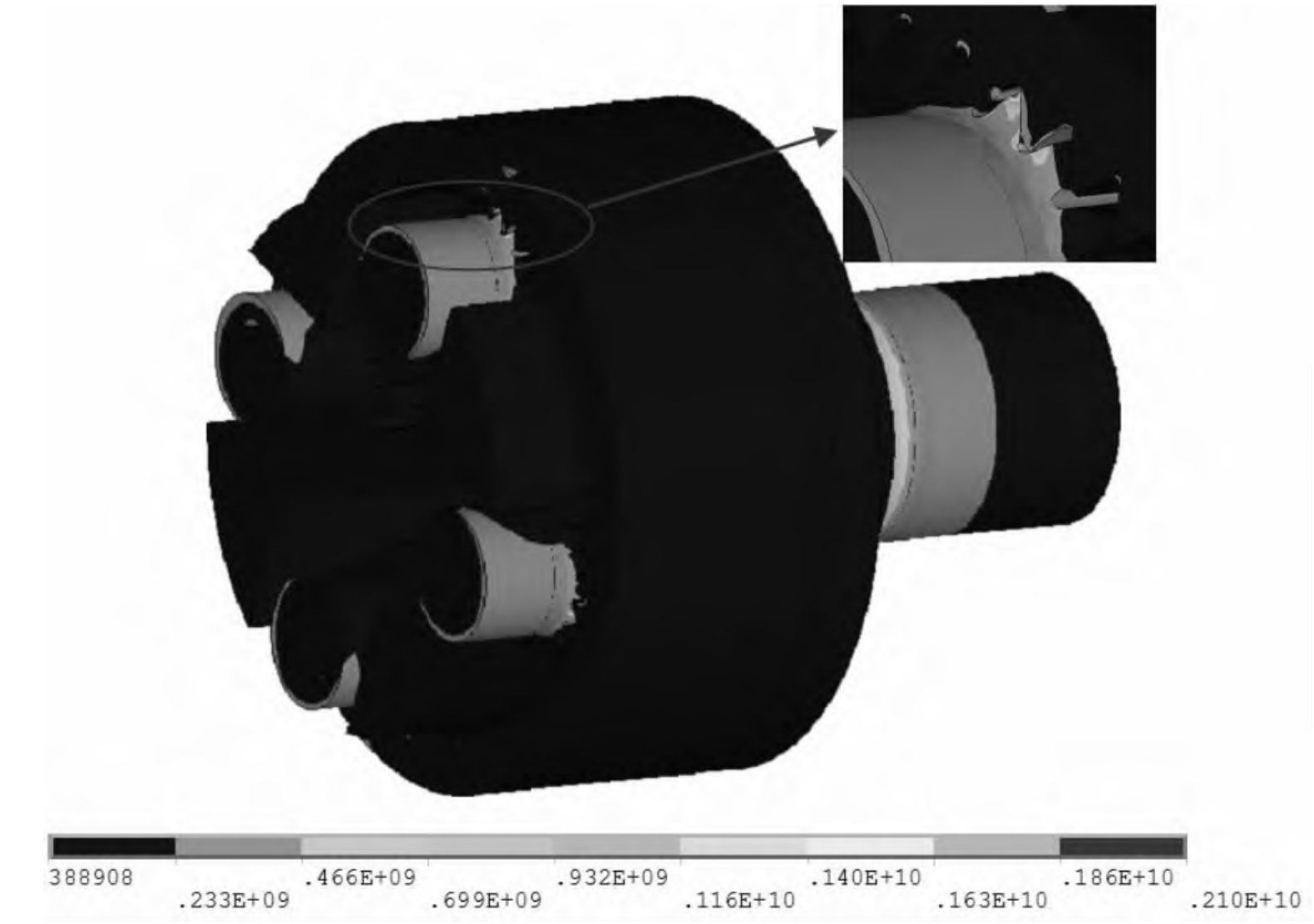
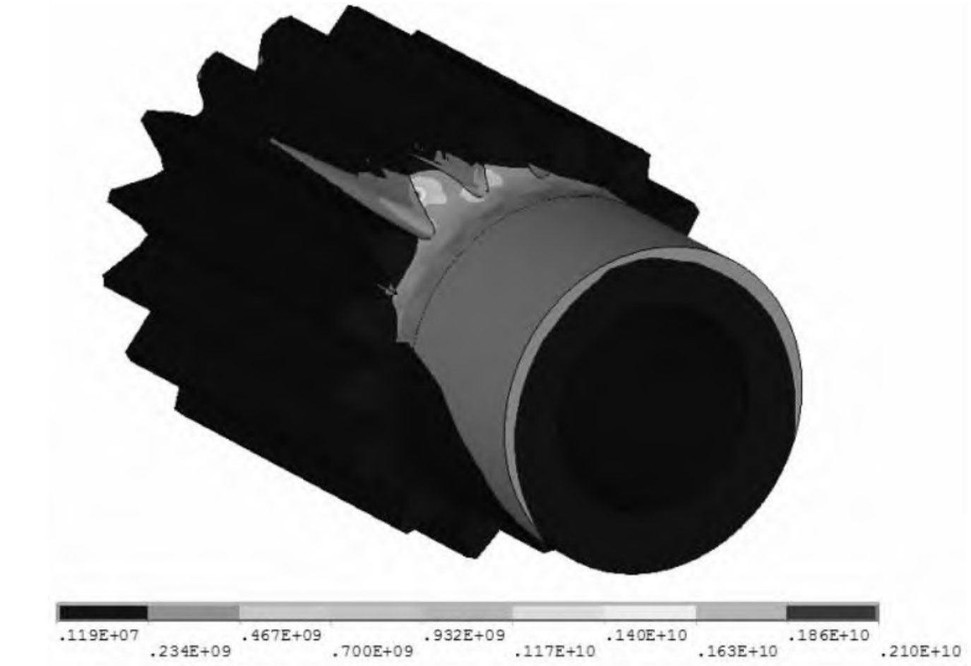
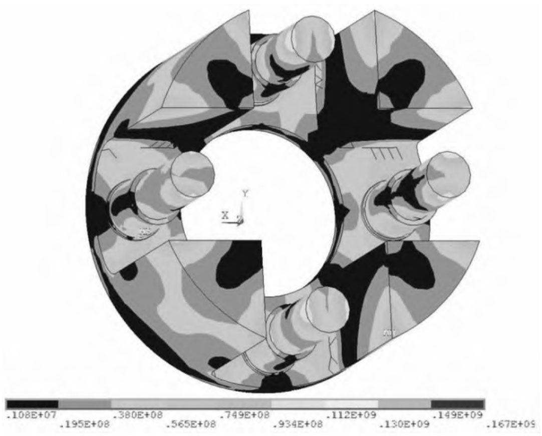
Through software analysis, it was found that under the maximum working load, the bending stress of the floating gear ring and planetary gear tooth root did not exceed the strength limit and fatigue limit; Under limited load, all parts do not exceed the static strength limit; Under extreme load, the bending stress of some gear teeth in the local bearing area is close to the static strength limit, but less than the allowable bending stress of the material, so the parts will not be damaged, as shown in Figure 11-13.
The improved product has completed life testing according to the load spectrum, and the functional performance test results meet the indicator requirements. After inspection, all planetary gears have no cracks, meeting the product life requirements.