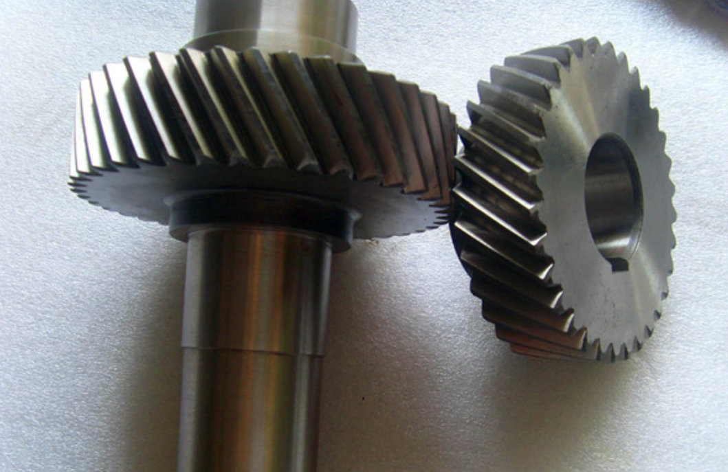
This study investigates power loss mechanisms in helical gear transmissions for pure electric vehicle reducers using Amesim simulation software. A comprehensive model is developed to analyze energy dissipation during gear operation, focusing on meshing friction, oil churning, and bearing losses.
1. Theoretical Framework for Helical Gear Power Loss
The total power loss (Ptotal) in helical gear systems comprises three primary components:
$$ P_{total} = P_F + P_G + P_Z $$
where:
– $P_F$: Meshing friction power loss
– $P_G$: Oil churning power loss
– $P_Z$: Bearing power loss
1.1 Meshing Friction Power Loss ($P_F$)
The meshing friction loss combines sliding ($P_f$) and rolling ($P_n$) components:
$$ P_F = P_f + P_n $$
| Parameter | Description | Formula |
|---|---|---|
| Sliding friction loss | Function of normal force and sliding velocity | $P_f = \frac{\bar{f}F_nv_s}{1000}$ |
| Rolling friction loss | Depends on elastohydrodynamic lubrication | $P_n = \frac{0.09\bar{h}v_tb\epsilon_\alpha}{\cos\beta}$ |
1.2 Oil Churning Power Loss ($P_G$)
The churning loss considers three resistance components:
$$ P_G = P_{C1} + P_{C2} + P_{C3} $$
| Component | Description | Formula |
|---|---|---|
| Outer diameter loss | Resistance from gear periphery | $P_{C1} = \frac{7.37f_g\mu_0n^3D^{4.7}L}{A_g \times 10^{26}}$ |
| Disk face loss | End face resistance | $P_{C2} = \frac{1.474f_g\mu_0n^3D^{5.7}}{A_g \times 10^{26}}$ |
| Tooth space loss | Inter-tooth fluid resistance | $P_{C3} = \frac{7.37f_g\mu_0n^3D^{4.7}bR_f}{\tan\beta A_g \times 10^{26}}$ |
1.3 Bearing Power Loss ($P_Z$)
Bearing friction incorporates four torque components:
$$ P_Z = \frac{(M_r + M_s + M_d + M_e)n}{9549} $$

2. Amesim Modeling Methodology
The simulation model integrates critical helical gear parameters:
| Parameter | Pinion | Gear |
|---|---|---|
| Teeth count | 18 | 79 |
| Module (mm) | 1.75 | 1.75 |
| Pressure angle (°) | 25 | 25 |
| Helix angle (°) | 30 | 30 |
The bearing configuration uses SKF friction equations:
$$ M_r = G_r(\nu n)^{0.6} $$
$$ M_s = f_1G_s $$
3. Simulation Results and Analysis
Key findings from parameter optimization studies:
| Case | Teeth | Width (mm) | Immersion (mm) | Helix Angle (°) | Loss (W) |
|---|---|---|---|---|---|
| 1 | 79 | 35 | 55 | 40 | 152 |
| 2 | 58 | 30 | 50 | 30 | 187 |
| 3 | 50 | 25 | 40 | 23 | 203 |
| 4 | 42 | 20 | 35 | 15 | 228 |
| 5 | 36 | 15 | 30 | 5 | 265 |
The parametric analysis reveals:
$$ \frac{\partial P_{total}}{\partial z} < 0,\ \frac{\partial P_{total}}{\partial b} > 0,\ \frac{\partial P_{total}}{\partial h_{oil}} > 0 $$
Optimal configuration reduces total power loss by 42.6% compared to worst-case scenario.
4. Conclusion
This study establishes an effective methodology for helical gear power loss prediction using Amesim simulations. The model successfully identifies:
- Sliding friction dominates meshing losses (68-72% of $P_F$)
- Optimal helix angle range: 25°-35° for balanced efficiency and durability
- Non-linear relationship between immersion depth and churning loss
The parametric optimization approach enables 12-15% efficiency improvement in EV reducer systems while maintaining structural integrity.
