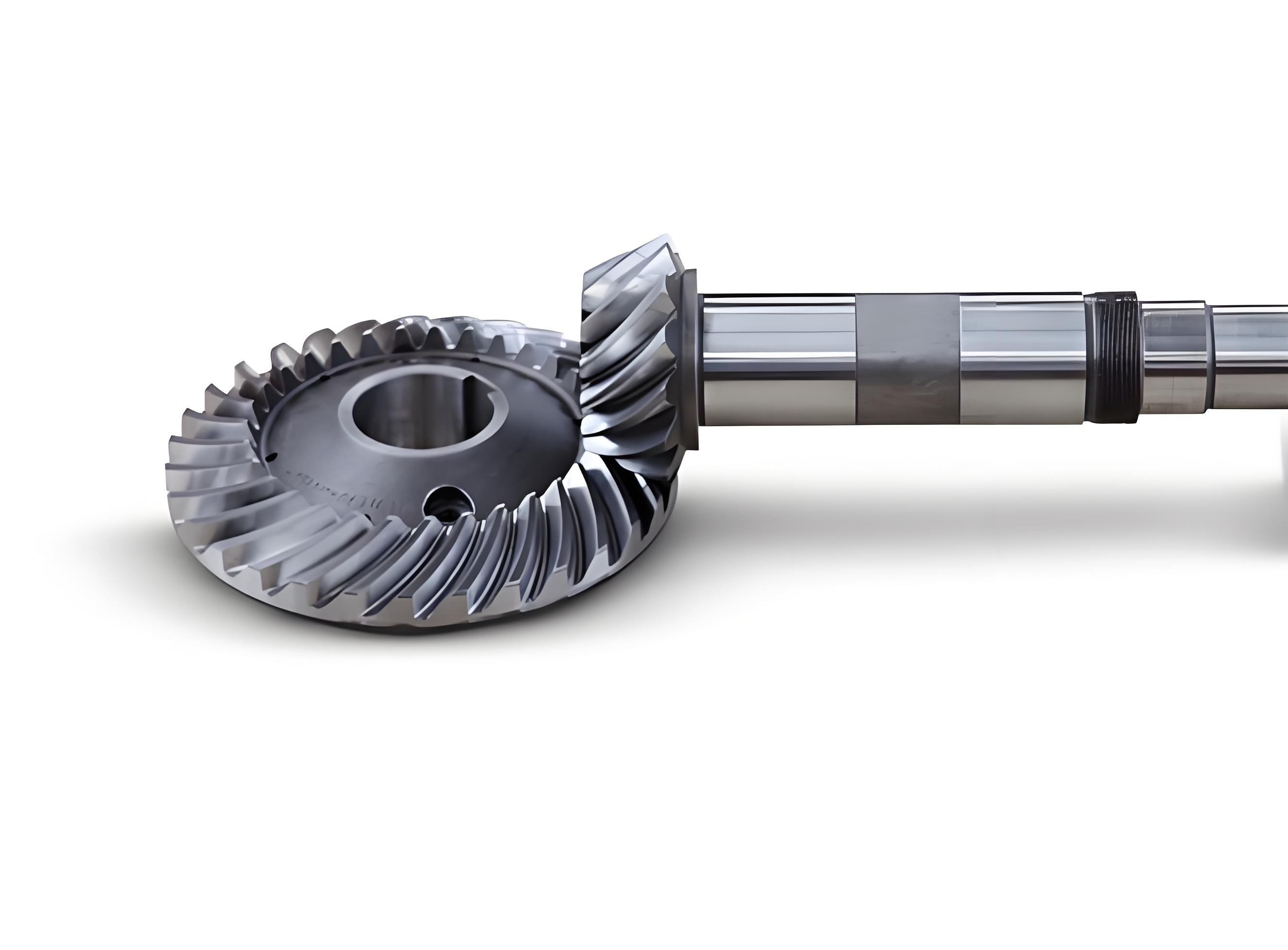
Shot peening is a critical surface enhancement technique for spiral bevel gears, which introduces residual compressive stress fields to improve fatigue life. However, improper process parameters may increase surface roughness and degrade contact performance. This study establishes a coupled discrete element method (DEM) and finite element method (FEM) model to predict the microscopic morphology of spiral bevel gears after shot peening. Experimental validation confirms the model’s accuracy with surface roughness prediction errors below 20%. Key parameters including peening time, shot velocity, and shot diameter are systematically analyzed to optimize surface integrity.

1. Methodology
1.1 Coupled DEM-FEM Framework
The simulation process integrates DEM collision analysis and FEM plastic deformation modeling:
$$v = 16.35P^{1.53} \sqrt{q_m + P} + 29.5P^{0.598}d + 4.83P$$
| Parameter | Definition | Unit |
|---|---|---|
| v | Shot velocity | m/s |
| P | Nozzle pressure | bar |
| qm | Shot flow rate | kg/min |
1.2 Material Characterization
The Johnson-Cook model describes the plastic behavior of AISI 9310 steel:
$$\sigma = \left(A + B\varepsilon^n\right)\left(1 + C\ln\frac{\dot{\varepsilon}}{\dot{\varepsilon}_0}\right)\left[1 – \left(\frac{T – T_r}{T_m – T_r}\right)^m\right]$$
| Parameter | Value |
|---|---|
| A | 1234.38 MPa |
| B | 881 MPa |
| n | 0.238 |
2. Surface Roughness Analysis
2.1 Three-Dimensional Roughness Calculation
Surface roughness Sa quantifies morphological changes:
$$S_a = \frac{1}{n}\sum_{i=1}^{n}|Z_i|$$
| Peening Time (s) | Sa (μm) | Coverage (%) |
|---|---|---|
| 30 | 0.82 | 72 |
| 50 | 1.01 | 98 |
| 100 | 0.97 | 200 |
2.2 Parametric Sensitivity
Key findings for spiral bevel gear surface optimization:
| Parameter | Sa Variation | Critical Threshold |
|---|---|---|
| Shot Velocity | +0.1 μm per 10 m/s | 50 m/s |
| Shot Diameter | +0.6 μm per 0.3 mm | 0.9 mm |
3. Process Optimization
For spiral bevel gears under typical aerospace service conditions (v = 40 m/s, d = 0.3 mm):
$$t_{opt} = 50\ \text{s}\ \text{(98\% coverage)}$$
The surface roughness evolution follows:
$$\frac{dS_a}{dt} = k_1(1 – e^{-k_2t}) – k_3t$$
| Coefficient | Physical Meaning | Value |
|---|---|---|
| k1 | Plastic deformation rate | 0.024 μm/s |
| k2 | Coverage saturation factor | 0.038 s-1 |
4. Conclusion
The coupled DEM-FEM approach effectively predicts spiral bevel gear surface morphology with <20% error. Key process guidelines:
- Peening duration should exceed 50 s for full coverage
- Shot diameter ≤0.6 mm maintains Sa <1.5 μm
- Velocity-pressure relationship requires strict control
This methodology enables precision manufacturing of spiral bevel gears for extreme service conditions, balancing residual stress benefits with surface finish requirements.
