The basic parameters of spiral bevel gears are shown in Table 1.
| Parameters | Driving wheel | Driven wheel |
| Number of teeth z | 30 | 76 |
| Rotating speed n/(r ∙ min-1) | 20900 | 7626 |
| Large end modulus mt/mm | 3.85 | 3.85 |
| Pressure angle αn/(°) | 20 | 20 |
| Helix angle β/ (°) | 30 | 30 |
| Tooth width B/mm | 38.5 | 38.5 |
| Axis angle σ/ (°) | 69.77 | 69.77 |
| Direction of rotation | Right | Right |
| Diameter of dividing circle D/mm | 103.95 | 284.9 |
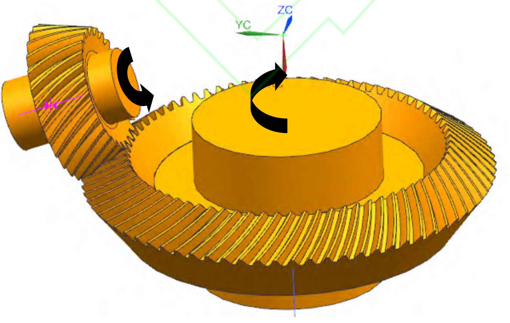
1) Modeling of Spiral Bevel Gear Pair
According to the local synthesis method proposed by Litvin, three basic processing parameters are preset. On the basis of controlling the meshing quality of spiral bevel gears, the processing parameters of driving gears can be designed and calculated. After determining the cutting parameters of spiral bevel gear, the tooth surface equation of spiral bevel gear can be obtained. Several coordinate points are obtained according to the tooth surface equation, and the surface is fitted in UG software according to these coordinate points to form a tooth surface that is very close to the actual tooth surface.
In order to simplify the numerical simulation complexity of windage loss and improve the simulation efficiency, it is necessary to simplify the model. The spiral bevel gear shaft is modeled as a solid shaft and all fillets, chamfers, bearings and connectors in the reduction gearbox are ignored. Assemble the modeled driving gear and driven gear. Since the mesh in the meshing area tends to be infinitesimal when the flow field is divided into meshes in the later stage, it is impossible to divide high-quality meshes. Therefore, adjust and properly cut the spiral bevel gear with standard assembly to keep 2-3 layers of boundary layer thickness between the meshing gear teeth. This method can ensure the mesh quality, and it can keep a small gap between the meshing teeth, As the spiral bevel gear is in point engagement, the existence of this kind of micro clearance has very little impact on the actual wind resistance, and can avoid the meshing friction loss caused by the spiral bevel gear engagement in the actual engagement. Only the wind resistance power loss is considered. The final model is shown in Figure 1.
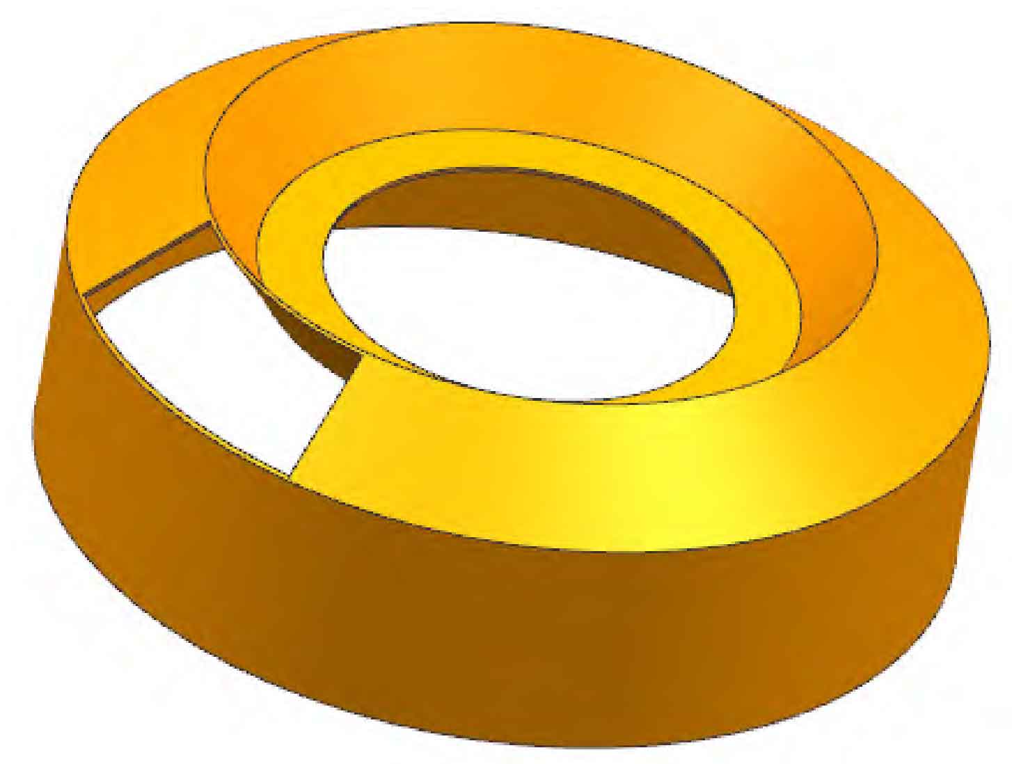
2) Windshield modeling
The structural design of the wind shield is shown in Figure 2. The wind shield is installed between the driven spiral bevel gear and the reduction gearbox, completely covering the driven gear tooth surface, and connected with the bottom of the main reduction gearbox through bolts. The wind shield is made of 45 steel.
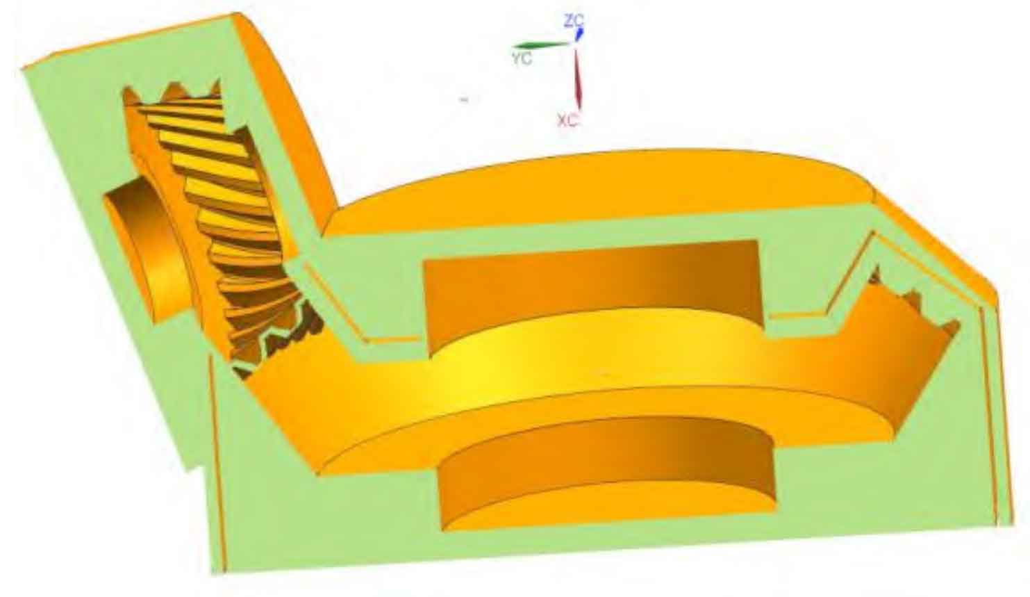
3) Flow field modeling
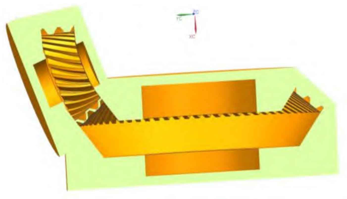
What needs to be concerned is the interaction between the air around the spiral bevel gear and the spiral bevel gear, so it is necessary to extract the flow field inside the reducer. Without considering the influence of the fine structure of the reducer box, the flow field model can be obtained from the reducer box and spiral bevel gear pair through Boolean operation. Figure 3 and Figure 4 below are sectional views of the simplified flow field calculation model inside the gearbox. Figure 3 shows the flow field calculation model without a wind shield, and Figure 4 shows the flow field calculation model with a wind shield; The solid part in the figure is the area between the inner wall of the box and the surface of the spiral bevel gear pair, that is, the flow field calculation domain. The hollow part is the spiral bevel gear pair and the wind shield entity. This part does not participate in the fluid control volume calculation.