
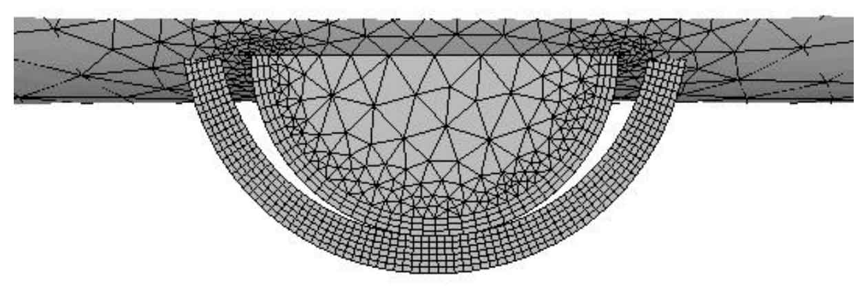
It is necessary to set up the parameters and mechanical model in the crack propagation process of spur gear by using FRANC3D and ANSYS to jointly simulate the crack propagation. The crack propagation is set as 8 steps, the propagation amount of each crack is 0.12mm, and the fracture criterion is selected as the strain energy release rate. According to the change trend of stress intensity factor obtained from the static analysis, FRANC3D automatically determines the morphology of crack front in the next step according to the set crack growth and divides the grid. It should be noted that the crack propagation amount of each step set here refers to the crack propagation amount on the default path of the system. In this paper, the default path of the system is the connecting line at the midpoint of the crack front edge. The crack propagation amount at other positions of the crack front edge of spur gear is converted according to the size of the stress intensity factor, and then the crack propagation amount on the whole crack front edge is obtained, Then the grid is automatically divided. Figure 1 is the set front edge of crack propagation of spur gear.
Finally, the simulation results of crack propagation of spur gear are obtained. Fig. 2 shows the crack propagation results under actual load.

In order to clearly compare the different crack propagation paths of spur gears under different tooth direction distributed loads, Fig. 3 shows the crack propagation path of spur gears on the tooth surface. The former is the propagation path under ideal uniform load and the latter is the propagation path under actual load.
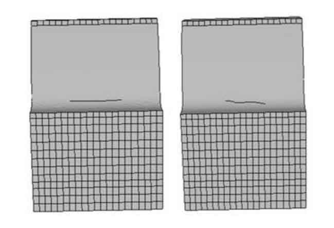
From the surface of spur gear, under the action of ideal uniform load, the path of spur gear crack on the surface of spur gear is basically parallel to the tooth top line, and the path tilts under the action of actual load. The results show that under the action of different loads, the path of crack propagation of spur gear on the surface of spur gear not only tilts to varying degrees, but also tilts on the midpoint line at the front edge of spur gear crack, as shown in Fig. 4.


From the path formed by the connection of the midpoint of the crack front edge of spur gear, under the ideal uniform load, the relationship between the holder of the midpoint connection at the crack front edge of spur gear and the y-axis is parallel, while under the actual load, the radial direction of the midpoint connection line at the crack front edge of spur gear gradually deviates to the direction of large load.
From the internal morphology after propagation, the crack surface of tooth root crack after propagation under ideal uniform load is basically parallel to the coordinate plane XZ, while the crack surface after propagation under actual load has a certain included angle with the XZ plane. Due to the different loads between the points on the contact line of spur gear under the actual load, the crack surface tilts near the direction of large load, that is, the crack propagation path deviates to the side of large load.
After the crack propagation of spur gear, the length of the midpoint connecting line at the front edge of the semi elliptical sheet crack is 0.84mm. On the surface of the crack body, the crack length of spur gear reaches 5-6mm. From this result, it can be seen that the semi elliptical sheet crack propagates from the two end points of the crack first, and the propagation rate and amount are greater than the deepest crack, The simulation results once again verify the theoretical analysis of stress intensity factor and propagation of semi elliptical sheet crack.
Now we analyze the change of semi elliptical flake crack morphology after crack propagation. When establishing the initial crack model, the short long shaft ratio is 0.8. After crack propagation of spur gear, the short long shaft ratio after crack propagation under ideal uniform load is about 0.60, and the short long shaft ratio after crack propagation under actual load is about 0.61, It can be seen that the geometry of the crack plane is also changing during the crack propagation of spur gears.