1 Gear matching scheme
In order to analyze the influence of the number of teeth, the number of planetary gears and the meshing phase on the characteristics of the sideband, five gear matching schemes are adopted. All schemes take the sun wheel as the input and the planet carrier as the output. Except scheme IV meets the condition (4.4), i.e. in-phase engagement, the others are all in continuous phase engagement, in which the number of teeth of scheme II and the number of planetary gears have a common factor of 2.
2 Transmission error
In order to reflect the influence of transmission error excitation as much as possible, the transmission error in each scheme is calculated, and the harmonic amplitude and phase of the first five order transmission error are extracted. For the convenience of comparison, straight teeth are adopted, the gear tooth width b = 20 mm, modulus MMN = 1.5, and input torque Tintin = 150 nm.
3 Simulation results and discussion
According to the given number of teeth, meshing phase, amplitude and phase of transmission error of each scheme, the rotation speed of planet carrier is set to be π 2C ω = π, the time-domain signal and frequency-domain signal are obtained by simulation, and the order is calculated according to the formula.

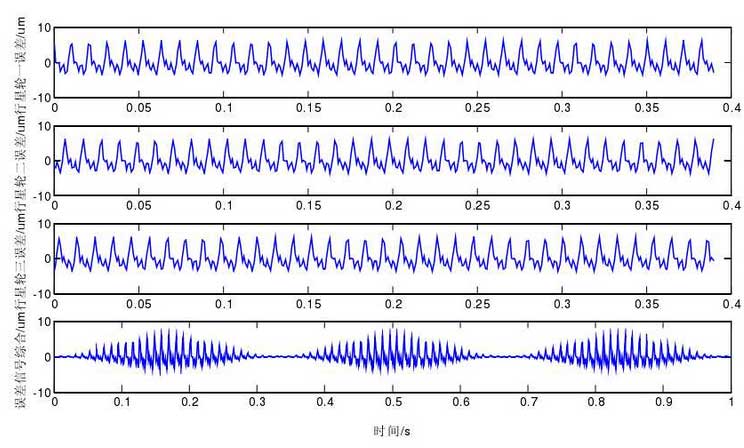
In the scheme I time domain signal shown in Figure 1, there is phase difference between the planetary gear transmission error time domain signals, indicating that each planetary gear is in different engagement positions at the same time, and it can be found that the signal x (T) at the measuring point, i.e. the comprehensive error signal, has obvious modulation phenomenon. In a cycle, three planetary wheels pass through the measuring points in turn.

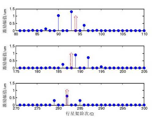
Figure 2 shows the scheme i-order distribution. The dotted line arrow indicates the first three order engagement order 94 (MIM Ω), 188 (2mim Ω), 282 (3im Ω) Im im Ω. The maximum amplitude of the first three harmonics appears in the side frequencies 93 (IMIM Ω – Ω), IIM C Ω – Ω), 189 (2IM C Ω + Ω) IIM C + Ω) 2IM C Ω + Ω), 282 (3 Ω) 3im Ω )In the vicinity of the side frequency, there is also a side frequency band with an interval of 3 im Ω (3 im Ω (IMP Ω) I Ω imp Ω), and the amplitude of the side frequency is asymmetric, while the amplitude of the first two main mesh orders is suppressed.

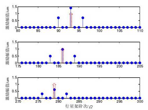
Fig. 3 shows the scheme IV order distribution. This scheme is in phase engagement. The maximum amplitude of the first three harmonics occurs at the main engagement order 93 (IV Ω m Ω IVM Ω), 186 (2 IVM Ω) IV Ω IVM Ω), 279 (3 IVM Ω) IVM Ω, and there is a symmetrical side frequency (3ivm L Ω± Ω IV Ω 3M C Ω± Ω) 3ivm Cl Ω± Ω) with an interval of 3ivm Ω IVM Ω 3 IV Ω.

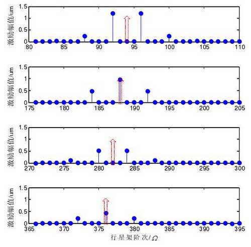
Fig. 4 shows the scheme II order distribution, the side frequency is symmetrical, the interval is 4ii, c4iic Ω, the maximum amplitude of the 2nd and 4th harmonics is 188 and 376 of the main mesh order, while the amplitude of the 1st and 3rd harmonics of the main mesh order is suppressed.
