
1. Simulation scheme design
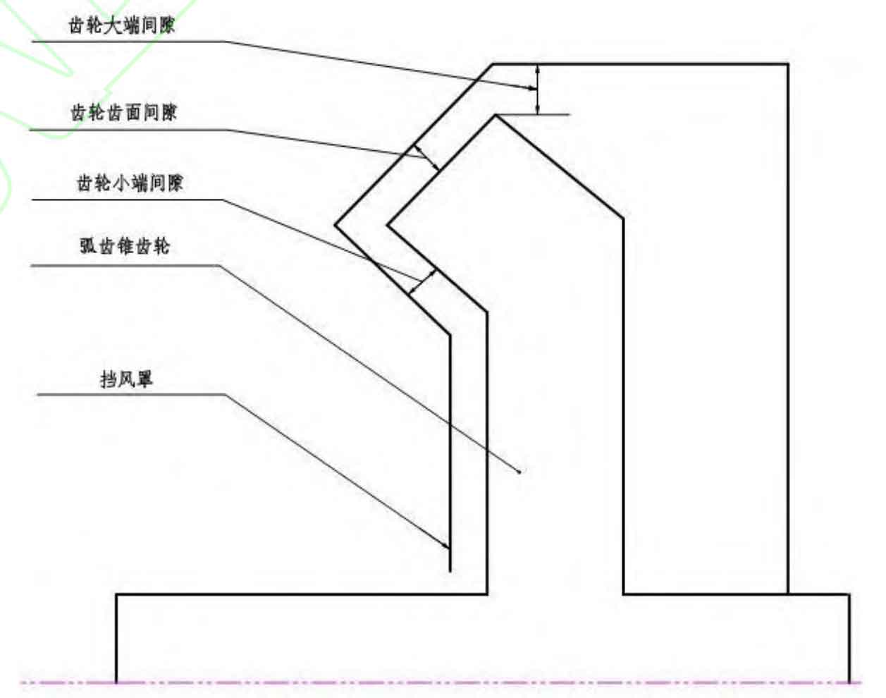
The numerical simulation calculation is carried out in two parts, one is the gearbox configuration without the wind shield, the other is the gearbox configuration with the wind shield installed. When the wind shield is installed, the clearance between different wind shields and spiral bevel gears is tested to obtain the local optimal wind shield configuration. The configuration parameters between the wind shield and the driven wheel include small end clearance, large end clearance, tooth surface clearance and meshing opening. The meshing opening refers to the opening angle of the wind shield at the engagement of two spiral bevel gears. Other parameters are shown in Figure 1.
2. Calculation of wind resistance power loss
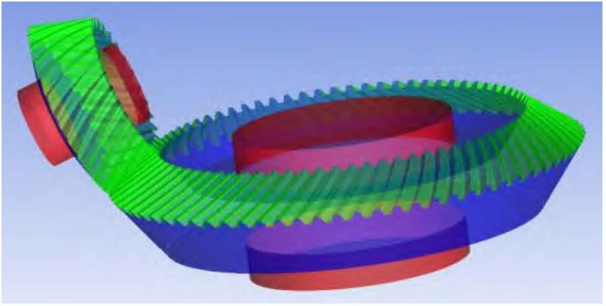
The windage torque acting on the tooth surface, end face and shaft surface of spiral bevel gear can be obtained by solving the software. The windage torque on the tooth surface is Tfi, the windage torque on the end face is Tdi, and the windage torque on the shaft surface is Tsi. As shown in Figure 2, the above three are the torque magnitude of air acting on the green, blue and red surfaces in the figure. The action line of wind resistance is taken as the axis line of each spiral bevel gear, and i is taken as 1 or 2, Represents the driving wheel and the driven wheel.
If the total wind resistance torque of a single spiral bevel gear is recorded as Ti, the total wind resistance power loss of the spiral bevel gear pair is:
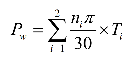
Where Pw is the total wind resistance power loss, Ti is the wind resistance torque of a single spiral bevel gear, in W, and T is in N.m.