
Controlling gear noise has become critical in modern manufacturing, directly impacting product quality and environmental compliance. Gear shaving remains a dominant finishing method for transmission gears due to its efficiency, cost-effectiveness, and ability to enhance precision, surface quality, and noise reduction through profile modification. However, intermittent tooth surface scratching during gear shaving significantly compromises surface integrity and acoustic performance. This analysis addresses the root causes and implements effective solutions.
Problem Manifestation
Scratches predominantly appear near tooth tips (Figure 1), absent in the mid-section. They exhibit parallel grooves aligned at a consistent angle to the involute direction, with uniform depth at identical curvature points. High-risk scenarios include:
- Soft materials or gears with high modification coefficients
- Aged gear shaving tools
- Excessive shaving allowances
- Degraded cutting fluids
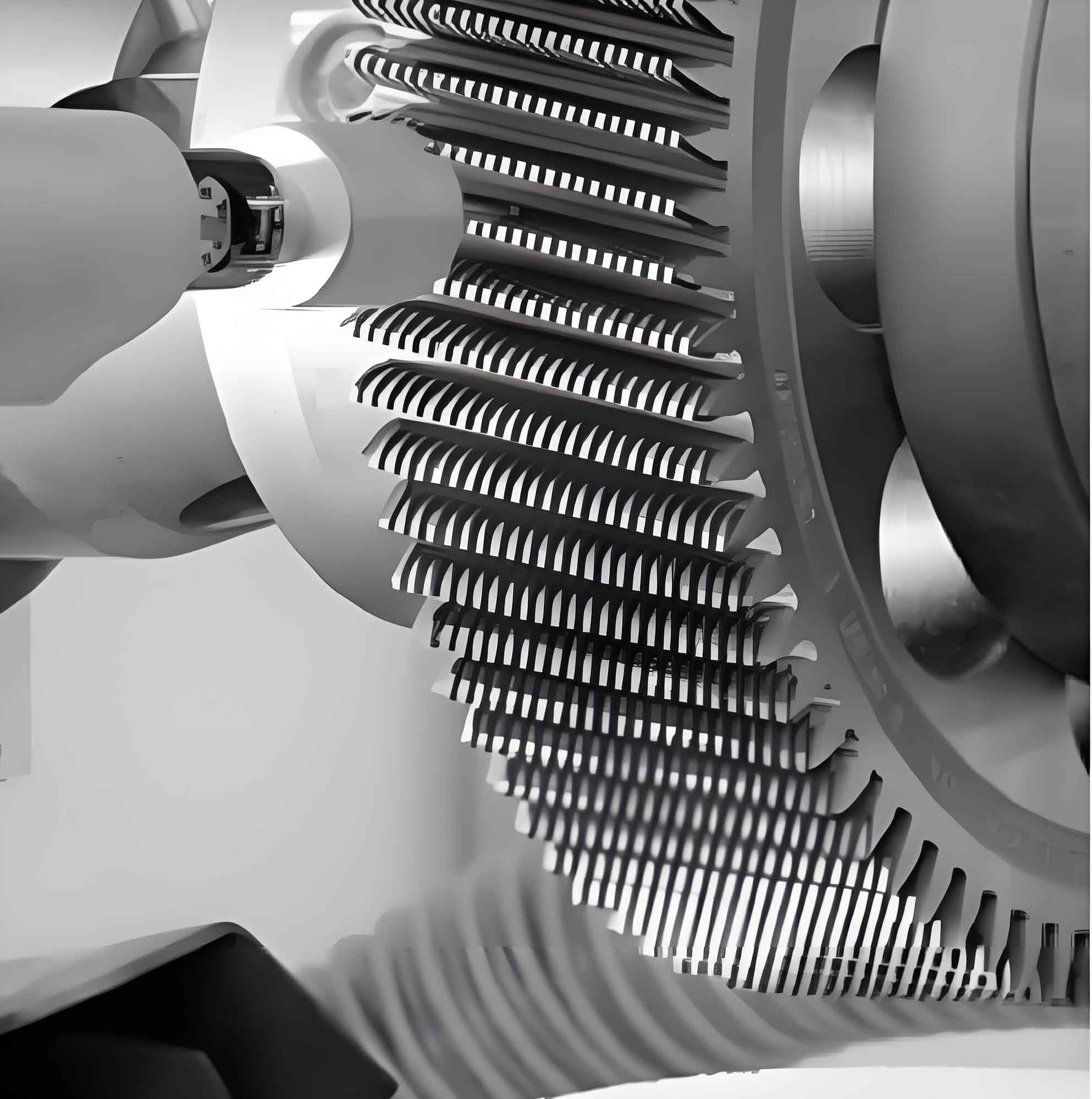
Gear Shaving Mechanics
Gear shaving utilizes crossed-axis helical gear meshing without backlash. The shaving cutter, featuring peripheral gashes forming cutting edges, drives the free-rotating workpiece at an axis crossing angle $\Sigma$. The fundamental cutting velocity stems from relative sliding motion:
$$v = v_0 \sin \Sigma$$
where $v_0$ is the cutter’s peripheral speed (m/min) and $\Sigma$ is the axis crossing angle (°). Material removal (0.005–0.010 mm) combines cutting and extrusion due to the tool’s zero clearance angle against the workpiece.
Contact Dynamics & Velocity Distribution
Conventional axial gear shaving creates elliptical contact zones moving along the tooth face, forming contact bands (Figure 5). Radial shaving achieves line contact across the face width. Crucially, cutting velocity varies along the tooth height:
$$v_c = v_0 \frac{\rho}{r_0}$$
where $\rho$ is the contact point radius and $r_0$ is the cutter pitch radius. Velocity peaks at the tooth tip (Figure 10), generating maximum heat. Simultaneously, involute meshing induces tangential sliding velocity ($v_t$), null at the pitch line but significant at tips/roots:
$$v_t = \omega \cdot r \cdot \tan\alpha$$
where $\omega$ is angular velocity, $r$ is contact point radius, and $\alpha$ is pressure angle.
| Position | Relative Velocity | Thermal Impact |
|---|---|---|
| Tooth Tip | $v_{c(max)}$, $v_{t(max)}$ | High |
| Pitch Line | $v_c$, $v_t = 0$ | Moderate |
| Tooth Root | $v_c$, $v_{t(high)}$ | High |
Root Cause: Chip Adhesion Mechanism
Scratches originate not from the tool geometry itself but from adhered chips. High cutting temperatures, particularly at tooth tips where:
- Cutting velocity peaks ($v_{c(max)}$)
- Cutter root engagement causes poor chip evacuation/cooling
cause workpiece material to adhere to cutting edges (Figure 9). These hardened particles act as secondary cutting edges. While the primary cutting motion ($v_c$) aligns with tool gashes, the tangential sliding velocity ($v_t$) drags adhered particles across the gear surface, creating scratches angled relative to the involute direction by vector summation:
$$\theta = \tan^{-1}\left(\frac{v_t}{v_c}\right)$$
Critical Factors Influencing Scratching
Experimental verification isolated key parameters impacting adhesion and scratching:
| Workpiece Material | Hardness (HBW) | Parts Before Scratching |
|---|---|---|
| FAS3420H | 150–161 | 1652 |
| FAS3420H | 165–172 | 2056 |
| FAS3420H | 190–199 | 1985 |
| Cutter Speed (rpm) | Radial Passes | Allowance (mm) | Scratching |
|---|---|---|---|
| 180 | 5 | 0.15 | Light |
| 180 | 3 | 0.15 | Severe |
| 240 | 5 | 0.15 | Severe |
| 240 | 5 | 0.10 | Light |
| 100 | 5 | 0.08 | None |
| Fluid Condition | Parts Before Scratching | Observation |
|---|---|---|
| Aged (>2 months) | Variable, early onset | Light Scratching |
| Contaminated (hydraulic oil) | Immediate | Severe Scratching |
| Fresh (no additives) | ~1536 | Moderate Onset |
| Fresh (lubricity/defoamer additives) | >2347 | Delayed Onset |
Tool condition is paramount: severely worn tools cause immediate scratching versus newly sharpened cutters. Radial gear shaving inherently reduces scratching risk versus axial methods by distributing cutting forces and heat over a contact band (Figure 4b) instead of a point (Figure 4a), lowering localized temperature and adhesion tendency.
Comprehensive Solutions for Scratch Elimination
Mitigation requires a systemic approach targeting thermal management and chip control:
- Material Selection: Optimize hardness (170-197 HBW) for balanced machinability and minimal adhesion.
- Cutting Fluid Management:
- Maintain strict concentration and pH levels
- Prevent tramp oil contamination (e.g., hydraulic leaks)
- Use additives enhancing lubricity, cooling, and defoaming
- Implement regular filtration and scheduled replacement
- Shaving Allowance & Pre-Shave Quality:
- Minimize allowance: $A_{min} = \Sigma(F_p, F_\beta, F_\alpha, C_{mod})$ where $F_p$ is pitch variation, $F_\beta$ is helix error, $F_\alpha$ is profile error, $C_{mod}$ is modification depth. Typically 0.06–0.10 mm for modules <10.
- Improve pre-shave gear quality to reduce required material removal.
- Cutting Parameters:
- Reduce cutter speed ($v_0$) within productivity limits
- Increase number of lighter radial passes over fewer heavy passes
- Optimize axial feed rate based on cutter gullet capacity
- Tooling Strategy:
- Implement strict tool life monitoring; regrind before flank wear exceeds 0.2mm
- Optimize gullet geometry for improved chip flow and coolant access
- Select coatings (e.g., TiAlN) reducing friction and built-up edge
- Process Selection: Prioritize radial gear shaving over axial methods. Its line contact:
- Reduces specific cutting pressure and heat generation
- Distributes wear, extending tool life
- Allows higher feeds, maintaining productivity at lower speeds
Results
Implementing these measures eliminated tooth tip scratching. Stable production exceeding 2 million gears demonstrates:
- Consistent high-quality surface finish
- Reduced gear meshing noise (verified by NVH testing)
- Increased tool life and process reliability
Conclusion
Gear shaving tooth surface scratching originates from chip adhesion driven by localized cutting heat, particularly at tooth tips due to velocity distribution and cooling challenges. The tangential sliding velocity component drags adhered particles across the surface. Successful elimination requires a holistic strategy: optimizing workpiece material, rigorously controlling cutting fluid, minimizing allowances through pre-shave quality, selecting appropriate cutting parameters, proactive tool management, and adopting radial gear shaving. This integrated approach ensures superior gear quality and acoustic performance.