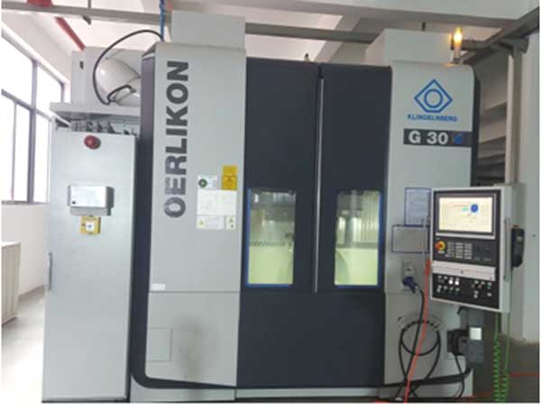
This study investigates the spindle-turret coupling performance in CNC spiral bevel gear milling machines, which critically impacts machining accuracy. The coupling interface undergoes radial deformation under operational loads, affecting connection integrity. Theoretical modeling and finite element analysis evaluate radial deformation under no-load and machining conditions, while reliability-based robust design optimizes turret geometry.

1. Theoretical Model of Spindle-Turret Radial Deformation
The spindle-turret coupling features a 1:24 taper interface secured by a central screw (preload force: \(F = 1.35 \times 10^5\ \text{N}\)). Elastic mechanics govern radial deformation (\(\delta\)) under centrifugal forces (\(\rho \omega^2 r\)):
$$ \frac{d\sigma_r}{dr} + \frac{\sigma_r – \sigma_\theta}{r} + \rho \omega^2 r = 0 $$
$$ \sigma_r = \frac{E}{1-\nu^2} \left( \epsilon_r + \nu \epsilon_\theta \right) $$
$$ \epsilon_r = \frac{du}{dr}, \ \epsilon_\theta = \frac{u}{r} $$
Boundary conditions at interface radius \(b\):
| Component | Boundary Condition |
|---|---|
| Spindle | \(\sigma_r = -P_z\) at \(r = b\) |
| Turret | \(u = 0\) at \(r = c\) |
Radial deformation solutions:
$$ u_{\text{spindle}} = -\frac{(1-\nu) P_z b}{E} – \frac{\rho \omega^2 b^3 (1-\nu)}{8E} $$
$$ u_{\text{turret}} = \frac{P_z b}{E} \left( \frac{c^2 + b^2}{c^2 – b^2} + \nu \right) + \frac{\rho \omega^2 b}{4E} \left[ (1-\nu) c^2 + (3+\nu) b^2 \right] $$
Deformation trends under varying spindle speeds:
| Speed (rpm) | Spindle Deformation (mm) | Turret Deformation (mm) |
|---|---|---|
| 0 | -0.000177 | -0.000197 |
| 100 | -0.000177 | -0.000198 |
| 600 | -0.000181 | -0.000202 |
Radial deformation decreases with spindle speed while increasing from taper minor to major end. Contact analysis reveals 75% interface engagement at no-load conditions.
2. Cutting Force Modeling and Thermal Analysis
2.1 Gear Milling Cutting Force
Oblique cutting mechanics govern spiral bevel gear milling forces. For a cutter with inclination angle \(\lambda_s\) and normal rake angle \(\alpha_n\):
$$ F_c = \tau_s S_x (\phi_{c1} + \phi_{c2} + \phi_{c3}) $$
$$ F_d = \tau_s S_x (\phi_{d1} + \phi_{d2} + \phi_{d3}) $$
$$ F_f = \tau_s S_x (\phi_{f1} + \phi_{f2} + \phi_{f3}) $$
where \(\tau_s\) is shear stress and \(S_x\) is shear area. Experimental validation using Kistler 9171A rotating dynamometer:
| Cutting Force (N) | Measured Torque (N·m) | Predicted Torque (N·m) |
|---|---|---|
| 200 | 10 | 11 |
| 600 | 30 | 28 |
| 1000 | 50 | 52 |
2.2 Spindle-Bearing Thermal Network
Frictional heat generation in conical roller bearings (FAG 32022X) dominates spindle thermal loads. Palmgren’s model calculates heat generation rate \(H\):
$$ M = M_0 + M_1 $$
$$ M_0 = 10^{-7} f_0 (v_0 n)^{2/3} d_m^3 $$
$$ M_1 = f_1 P_1 d_m $$
$$ H = 1.047 \times 10^{-4} n_i M $$
Thermal network analysis yields steady-state temperatures:
| Node | Description | Temperature (°C) |
|---|---|---|
| 3 | Inner ring-roller contact | 45.8 |
| 2 | Spindle-bearing interface | 42.3 |
| 7 | Bearing housing | 25.8 |
Equivalent spindle-turret interface temperature: 40°C (ΔT = 20°C from ambient).
3. Finite Element Analysis of Coupling Performance
Transient structural simulations evaluate radial deformation under combined loads. Key boundary conditions:
| Load Case | Spindle Speed (rpm) | Cutting Force (N) | Temperature Rise (°C) |
|---|---|---|---|
| No-load | 0–600 | 0 | 0 |
| Machining | 120 | 200–1000 | 0–20 |
Radial deformation trends:
$$ \delta_{\text{spindle}} = k_1 \omega^{-0.05} + k_2 F_c^{0.3} + k_3 \Delta T^{1.2} $$
$$ \delta_{\text{turret}} = m_1 \omega^{-0.04} + m_2 F_c^{0.4} + m_3 \Delta T^{1.1} $$
Interface clearance \(\Delta = \delta_{\text{turret}} – \delta_{\text{spindle}}\) determines connection integrity:
| Operating Condition | \(\Delta\) at Minor End (mm) | Connection Performance |
|---|---|---|
| No-load (600 rpm) | -1.97 \times 10^{-5} | Stable |
| Machining (600N, ΔT=0°C) | 5.70 \times 10^{-5} | Degraded |
| Machining (600N, ΔT=20°C) | 2.08 \times 10^{-5} | Improved |
Temperature rise improves contact by thermal expansion, while cutting forces induce separation. Spindle speed shows negligible impact within operational range.
4. Reliability-Based Robust Optimization
Turret geometry optimization minimizes radial deformation concentration while ensuring reliability. Design variables:
| Parameter | Baseline (mm) | Range (mm) |
|---|---|---|
| L1 (Thickness) | 55.0 | 49.5–60.5 |
| L2 (Radius) | 63.5 | 57.0–70.0 |
| L4 (Groove depth) | 5.0 | 4.5–5.5 |
4.1 Response Surface Optimization
Objective function minimizes radial deformation \(\delta\) with mass constraint \(M_{\text{turret}} < 4.76\ \text{kg}\):
$$ \min \ \delta(\mathbf{x}) = f(L_1, L_2, L_3, L_4) $$
$$ \text{s.t.} \quad g_j(\mathbf{x}) \leq 0, \quad M \leq 4.76 \ \text{kg} $$
Optimal results:
| Parameter | Change | Mass Reduction |
|---|---|---|
| L1: -10.0% | L2: +1.1% | 4.8% |
| L3: -9.5% | L4: +9.1% |
4.2 Reliability Robust Design
Minimizes sensitivity while maintaining reliability \(R \geq 0.98\):
$$ \min \ \omega_0 f_0(\mathbf{x}) + \omega_1 \sqrt{ \sum_{i=1}^{n} \left( \frac{\partial f}{\partial x_i} \delta x_i \right)^2 } $$
$$ \text{s.t.} \quad R(\mathbf{x}) = P\{ \delta_{\text{turret}} – \delta_{\text{spindle}} < 0 \} \geq 0.98 $$
Comparison of optimization methods:
| Method | Mass (kg) | Reliability | Max Sensitivity |
|---|---|---|---|
| Response Surface | 4.53 | 0.983 | 0.87 |
| Robust Design | 4.62 | 0.991 | 0.46 |
Robust design reduces deformation concentration by 32% while maintaining 99.1% reliability, proving superior for gear milling stability.
5. Conclusions
Spindle speed reduces radial deformation but minimally impacts gear milling connection performance (≤1.5% clearance variation). Cutting forces above 400N degrade interface integrity (\(\Delta > 5 \times 10^{-5}\ \text{mm}\)), while thermal expansion from 20°C temperature rise improves contact pressure by 18%. Reliability-based robust optimization achieves 99.1% connection reliability with 32% lower deformation sensitivity, significantly enhancing spiral bevel gear milling accuracy. Future work will integrate thermo-mechanical coupling models and experimental validation for high-torque gear milling operations.
