
In the realm of mechanical transmission systems, spiral bevel gears play a pivotal role due to their superior performance characteristics. As an engineer involved in gear manufacturing, I have witnessed firsthand the challenges associated with the machining and adjustment of spiral bevel gears. These gears are essential in applications such as machine tools and automotive differentials, where smooth operation, high load capacity, and minimal noise are paramount. Unlike straight bevel gears, spiral bevel gears feature curved teeth that engage gradually, reducing impact and vibration. However, this advantage comes at the cost of complex machining processes, where precise adjustments of the cutting tool and machine settings are critical. To address this, our team at a leading manufacturing facility developed a comprehensive program package dedicated to the calculation of cutting adjustments for spiral bevel gears. This article, written from my perspective as a developer, delves into the design philosophy, functionality, structure, and operational principles of this program package, emphasizing its application in real-world scenarios.
The core challenge in manufacturing spiral bevel gears lies in the intricate calculations required for gear blank geometry and machine adjustment parameters. Traditional manual methods are not only time-consuming but also prone to errors, as a single miscalculation can propagate through subsequent steps, compromising gear quality. Moreover, existing calculation methods often lack completeness and accuracy, leading to suboptimal gear performance. Recognizing these issues, we embarked on a project to create a reliable, efficient, and user-friendly solution. Our program package, built using the BASIC programming language, operates on microcomputers such as the Great Wall 0520, leveraging its computational power to deliver rapid and accurate results. The package is designed to handle various aspects of spiral bevel gear production, from geometric dimensioning to strength verification and cutting adjustment generation for different铣齿机 models.
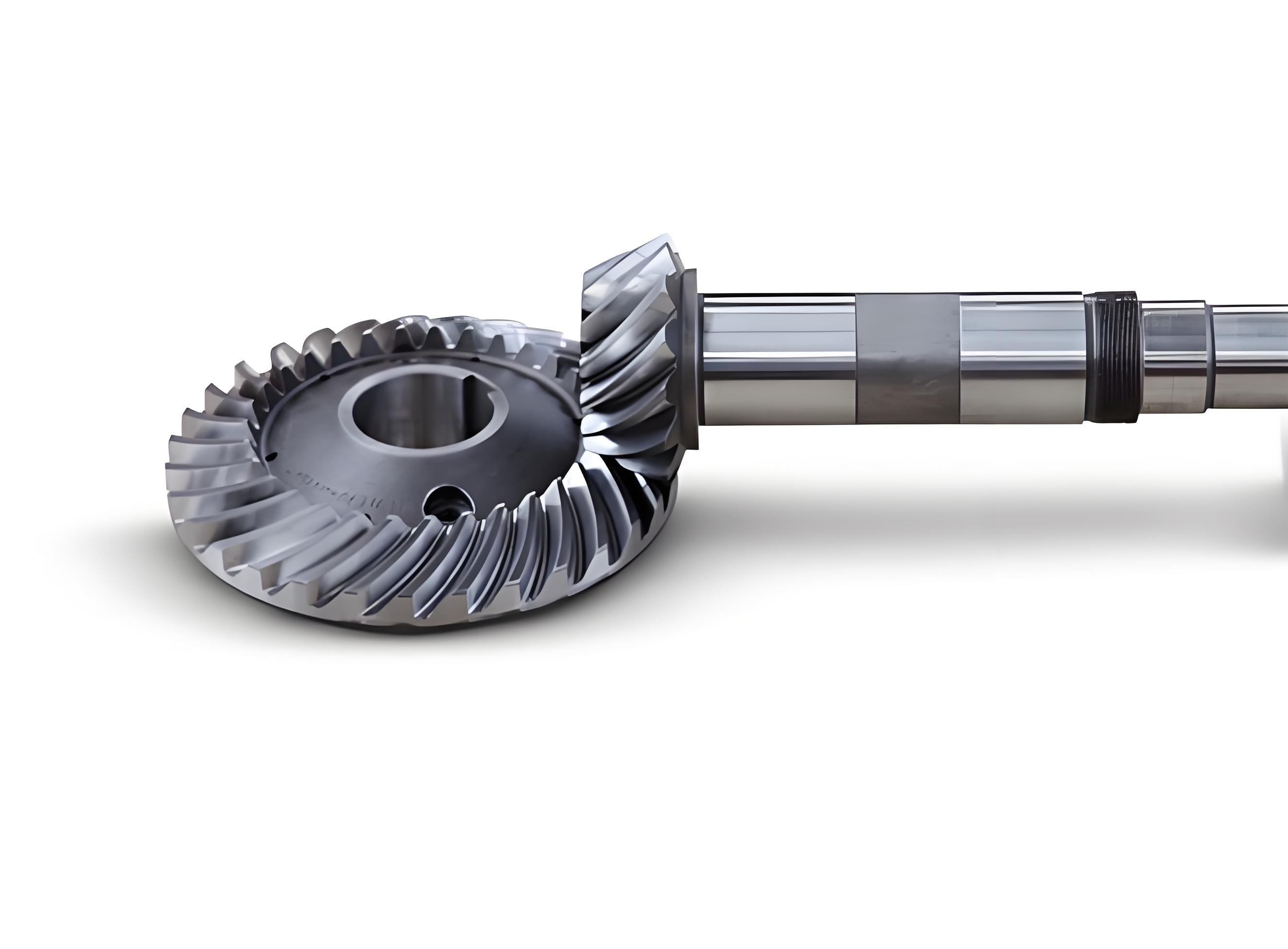
The program package is structured around a modular architecture, consisting of a main control program and several functional programs. Each functional program is dedicated to a specific task, such as calculating gear blank dimensions or generating adjustment cards for particular machine types. This modular approach ensures clarity, ease of maintenance, and scalability. The main control program serves as the central hub, presenting a menu of available functions and allowing users to select the desired operation. Alternatively, experienced users can directly invoke functional programs by name, bypassing the menu for faster access. The entire system is designed with a focus on accuracy, speed, and practicality, incorporating self-diagnostic checks to validate data integrity and operational correctness. For instance, during initialization, the program performs test calculations to verify that disk contents are intact and the machine is functioning properly, halting execution if discrepancies are detected.
From a design perspective, our primary goals were to ensure reliability, efficiency, and user-friendliness. To achieve reliability, we implemented closed-loop program structures and self-diagnostic mechanisms that monitor input data and intermediate results. If any parameter, such as the number of teeth, module, spiral direction, or cutter diameter, falls outside permissible ranges, the program automatically stops and notifies the operator via on-screen prompts. This prevents erroneous outputs that could lead to manufacturing defects. For efficiency, each functional program is independent and optimized for speed, minimizing disk read/write operations and reducing computational overhead. The program can process multiple data sets consecutively without restarting, and adjustment cards can be printed in multiple copies as needed. Practicality is enhanced through intuitive interfaces; all inputs and outputs are in Chinese characters (though for this article, we describe it in English), with clear prompts and formatted printouts that are ready for use in production workshops without additional editing.
The functionality of the program package is broadly categorized into three areas: gear blank geometry calculation, gear strength verification, and cutting adjustment calculation. Each category addresses a critical phase in the production of spiral bevel gears. Below, I outline these functionalities in detail, supported by tables and formulas to illustrate the underlying computations.
Gear Blank Geometry Calculation: This function computes the geometric dimensions of spiral bevel gear blanks based on input parameters. The initial parameters required are:
- Part numbers for the pinion and gear
- Number of teeth for both pinion and gear
- Module
- Spiral direction of the pinion (left-hand or right-hand)
- Face width
From these inputs, the program calculates a comprehensive set of geometric elements, such as pitch diameters, cone angles, addendum, dedendum, and whole depth. The calculations adhere to established gear design principles, ensuring compatibility with standard manufacturing practices. For example, the pitch diameter \( D \) is derived from the module \( m \) and number of teeth \( Z \):
$$ D = m \times Z $$
Similarly, the cone angle for the pinion \( \delta_1 \) and gear \( \delta_2 \) in a pair of spiral bevel gears can be computed using the shaft angle \( \Sigma \) and tooth ratios:
$$ \tan \delta_1 = \frac{\sin \Sigma}{Z_2 / Z_1 + \cos \Sigma} $$
$$ \delta_2 = \Sigma – \delta_1 $$
These formulas are embedded within the program to automate the derivation of all necessary dimensions.
| Parameter | Symbol | Formula | Description |
|---|---|---|---|
| Module | \( m \) | Input | Basic size parameter |
| Number of Teeth (Pinion) | \( Z_1 \) | Input | Teeth count on smaller gear |
| Number of Teeth (Gear) | \( Z_2 \) | Input | Teeth count on larger gear |
| Pitch Diameter (Pinion) | \( D_1 \) | \( D_1 = m \times Z_1 \) | Diameter at pitch cone |
| Pitch Diameter (Gear) | \( D_2 \) | \( D_2 = m \times Z_2 \) | Diameter at pitch cone |
| Cone Angle (Pinion) | \( \delta_1 \) | \( \tan \delta_1 = \frac{\sin \Sigma}{Z_2/Z_1 + \cos \Sigma} \) | Angle of pinion axis |
| Cone Angle (Gear) | \( \delta_2 \) | \( \delta_2 = \Sigma – \delta_1 \) | Angle of gear axis |
| Face Width | \( b \) | Input | Width of gear tooth |
Gear Strength Verification: This function assesses the bending stress and contact stress of spiral bevel gears under specified operating conditions. The input parameters include:
- Part numbers for pinion and gear
- Number of teeth, module, and face width
- Rated power
- Rotational speed of the pinion
Using these inputs, the program applies strength formulas based on gear theory. For bending stress \( \sigma_b \), a modified Lewis equation is used, accounting for the spiral angle and load distribution:
$$ \sigma_b = \frac{F_t}{b m_n Y} K_v K_o K_m $$
where \( F_t \) is the tangential force, \( b \) is face width, \( m_n \) is normal module, \( Y \) is the Lewis form factor, and \( K_v \), \( K_o \), \( K_m \) are velocity, overload, and mounting factors, respectively. For contact stress \( \sigma_c \), the Hertzian contact formula is adapted:
$$ \sigma_c = Z_E \sqrt{\frac{F_t}{b d_1} \frac{u+1}{u} K_v K_o K_m} $$
where \( Z_E \) is the elasticity factor, \( d_1 \) is the pinion pitch diameter, and \( u \) is the gear ratio. The program computes these stresses and compares them to allowable limits, ensuring the spiral bevel gears meet safety requirements.
| Parameter | Symbol | Unit | Description |
|---|---|---|---|
| Rated Power | \( P \) | kW | Power transmitted |
| Pinion Speed | \( n_1 \) | rpm | Rotational speed |
| Gear Ratio | \( u \) | – | \( u = Z_2 / Z_1 \) |
| Tangential Force | \( F_t \) | N | \( F_t = \frac{2T_1}{d_1} \) |
| Torque (Pinion) | \( T_1 \) | Nm | \( T_1 = \frac{9.55 \times 10^6 P}{n_1} \) |
Cutting Adjustment Calculation: This is the core functionality, generating adjustment cards for various spiral bevel gear铣齿机 models, such as the Gleason No. 116, No. 118, and others. It supports multiple machining methods, including single-index single-side, single-index double-side, and fixed adjustment methods. The input parameters are more extensive, typically involving 15 items:
- Part numbers for pinion and gear
- Number of teeth, module, spiral direction, and face width
- Additional machine-specific parameters like cutter diameter, pressure angle, and spiral angle
The program computes over 20 adjustment values, including machine settings (e.g., cutter tilt, swivel angle), gear train ratios, and inspection angles. A key feature is its ability to automatically adjust parameters if constraints are violated; for example, if the calculated number of teeth for a gear train is below the allowable minimum, the program increments it until the condition is satisfied. This iterative process ensures that the output adjustments are feasible for manufacturing.
The mathematical models for cutting adjustments are derived from gear generation principles. For instance, the cutter position relative to the gear blank is determined by the machine’s kinematic chain. The basic relationship for the rolling motion between the cradle and the gear blank is given by:
$$ \frac{\omega_c}{\omega_w} = \frac{Z_w}{Z_c} $$
where \( \omega_c \) is the cradle angular velocity, \( \omega_w \) is the workpiece angular velocity, \( Z_w \) is the number of teeth on the gear, and \( Z_c \) is the number of teeth in the generating gear. This ratio is implemented through change gears, which the program calculates precisely. Additionally, the cutter radial setting \( S_r \) and angle setting \( q \) are computed using formulas that account for the spiral bevel gear’s geometry:
$$ S_r = \frac{D_c}{2} + \Delta R + x_t m $$
$$ q = \arctan\left(\frac{\sin \beta}{\cos \delta + \cos \beta \sin \delta}\right) $$
Here, \( D_c \) is the cutter diameter, \( \Delta R \) is the cutter radius correction, \( x_t \) is the tangential shift coefficient, \( \beta \) is the spiral angle, and \( \delta \) is the pitch cone angle. These formulas are integral to achieving accurate tooth profiles on spiral bevel gears.
| Adjustment Item | Symbol | Unit | Calculation Basis |
|---|---|---|---|
| Cutter Tilt Angle | \( \alpha_t \) | degrees | Based on pressure angle and spiral angle |
| Cutter Swivel Angle | \( \gamma \) | degrees | Function of gear geometry and machine type |
| Radial Setting | \( S_r \) | mm | Derived from cutter diameter and corrections |
| Change Gear Ratio | \( i \) | – | Ratio of generating gear teeth to workpiece teeth |
| Machine Center to Back | \( X \) | mm | Distance from machine center to gear back face |
| Blank Offset | \( \Delta X \) | mm | Offset for tooth depth control |
The program structure is designed for robustness and ease of use. Each functional program follows a similar workflow: initialization, input validation, computation, and output. During initialization, constants such as standard cutter dimensions, correction factors, and coefficients are loaded into memory. The program then prompts the user for input data, with on-screen hints in Chinese characters (e.g., “Enter part number,” “Enter number of teeth”). After data entry, the program checks for validity; if any input is out of range, it requests re-entry. Once validated, the computation proceeds automatically, leveraging optimized algorithms to perform recursive calculations efficiently. Finally, the results are formatted into an adjustment card and sent to the printer. The card includes all necessary settings in a clear, tabular format, ready for use by machine operators.
To illustrate the program’s capabilities, let me present a calculation example for a pair of spiral bevel gears. Suppose we have a pinion and gear with the following specifications:
- Pinion part number: P-001, Gear part number: G-001
- Pinion teeth: \( Z_1 = 16 \), Gear teeth: \( Z_2 = 32 \)
- Module: \( m = 4 \, \text{mm} \)
- Spiral direction: Left-hand for pinion
- Face width: \( b = 30 \, \text{mm} \)
- Shaft angle: \( \Sigma = 90^\circ \)
Using the gear blank geometry function, the program computes the geometric dimensions. For instance, the pitch diameters are:
$$ D_1 = 4 \times 16 = 64 \, \text{mm} $$
$$ D_2 = 4 \times 32 = 128 \, \text{mm} $$
The cone angles are calculated as:
$$ \tan \delta_1 = \frac{\sin 90^\circ}{32/16 + \cos 90^\circ} = \frac{1}{2} = 0.5 \Rightarrow \delta_1 = 26.565^\circ $$
$$ \delta_2 = 90^\circ – 26.565^\circ = 63.435^\circ $$
These results, along with others like addendum and dedendum, are output in a detailed report.
For cutting adjustment, assume we are using a Gleason No. 116 machine with a single-index double-side method. Input additional parameters such as cutter diameter \( D_c = 152.4 \, \text{mm} \), pressure angle \( \alpha = 20^\circ \), and spiral angle \( \beta = 35^\circ \). The program then computes adjustments like the cutter tilt angle \( \alpha_t \), which might be derived as:
$$ \alpha_t = \alpha + \Delta \alpha $$
where \( \Delta \alpha \) is a correction based on the spiral bevel gear’s specific geometry. Similarly, the change gear ratio \( i \) for the generating motion is:
$$ i = \frac{Z_c}{Z_w} $$
where \( Z_c \) is the number of teeth in the imaginary generating gear, often set to a standard value like 120. The program determines the appropriate change gears from a library of available gears to approximate this ratio. The output adjustment card includes these values, along with settings for machine axes and inspection angles.
| Item | Value | Remarks |
|---|---|---|
| Machine Type | Gleason No. 116 | – |
| Machining Method | Single-Index Double-Side | – |
| Cutter Diameter | 152.4 mm | 6 inches |
| Cutter Tilt Angle | 21.5° | Adjusted for spiral angle |
| Cutter Swivel Angle | 15.2° | – |
| Radial Setting | 78.3 mm | Including corrections |
| Change Gears (Driven/Driver) | 48/24 | Ratio = 2.0 |
| Machine Center to Back | 120.0 mm | – |
| Blank Offset | 0.5 mm | For fine-tuning |
| Roll Check Angle (Cradle) | 145.6° | For quality inspection |
| Roll Check Angle (Workpiece) | 72.8° | For quality inspection |
The program’s effectiveness has been validated through extensive testing in production environments. By using this program package, manufacturers can achieve significant improvements in the quality of spiral bevel gears. The calculated adjustments lead to optimal tooth contact patterns, reducing the need for post-machining corrections and minimizing scrap rates. Moreover, the rapid computation speeds up the pre-production phase, allowing for shorter design cycles and faster response to customer demands. In one case study, the time required to generate adjustment cards was reduced from several hours manually to under a minute with the program, while accuracy improved markedly, as evidenced by consistent gear performance in assembly tests.
In conclusion, the spiral bevel gear cutting adjustment calculation program package represents a significant advancement in gear manufacturing technology. From my experience as a developer, I can attest to its robustness and utility. The modular design, coupled with rigorous mathematical models, ensures reliable outputs for a wide range of spiral bevel gear configurations. By automating complex calculations, it not only enhances productivity but also contributes to the broader adoption of spiral bevel gears in high-performance applications. Future developments may include integration with CAD/CAM systems and expansion to accommodate new machine types or advanced gear designs. However, the current version stands as a testament to the power of computational tools in solving intricate engineering challenges associated with spiral bevel gears.
Throughout this article, I have emphasized the importance of spiral bevel gears in modern machinery and the critical role of precise calculations in their manufacture. The program package described herein is a practical solution that embodies years of research and practical insights. It is my hope that this detailed exposition will inspire further innovation in the field and assist engineers in leveraging such tools to achieve excellence in gear production. As the demand for efficient and quiet transmissions grows, the relevance of spiral bevel gears and the software supporting their manufacture will only increase, driving progress in mechanical engineering and industrial automation.