
In the realm of power transmission systems for intersecting or skew axes, such as those critical in aerospace and automotive applications, spiral bevel gears serve as fundamental components. The performance of these gears is heavily influenced by the tooth contact pattern—its shape, size, and location directly impact noise, vibration, and load-bearing capacity. Traditional gear cutting methods, particularly those based on the Gleason system, often introduce a detrimental phenomenon known as diagonal contact, especially pronounced in external diagonal contact. This issue arises because these methods only ensure equal pressure angles at a single designated calculation point on the tooth flank. Away from this point, pressure angle errors accumulate due to spiral angle variations, leading to an elongated, diagonal contact zone that reduces effective contact area and compromises performance under heavy loads. To address this fundamental limitation and enhance the efficiency of the gear cutting process by eliminating the need for extensive trial-and-error adjustments, I have developed and explored a novel machining approach termed the Spread-Out Helix Modified Roll method. This article delves into the underlying principles, mathematical formulation, virtual simulation, and experimental validation of this advanced gear cutting technique.
The core innovation of the Spread-Out Helix Modified Roll method lies in its reorientation of the cutter axis during the gear cutting process for the pinion. In conventional generating methods, the cutter axis for both the gear and pinion is typically installed perpendicular to their respective root cones to simultaneously generate the tooth flank and root fillet. This arrangement results in non-parallel cutter axes, which is the root cause of the diagonal contact. In contrast, my proposed method for gear cutting dictates that the gear is cut using a standard generating method with its cutter axis perpendicular to the gear’s root cone. However, for the pinion, the cutter axis is installed perpendicular to an equidistant surface related to the gear’s root cone—specifically, the pinion’s face cone. This strategic alignment ensures that the cutter axes for both members become parallel. Consequently, the generating surface of the gear cutter and the complementary surface of the pinion cutter become congruent along the pitch cone direction. This geometrical harmony, established during the gear cutting operation, theoretically eliminates the inherent tendency for diagonal contact from its very origin. To achieve a tapered tooth form (standard Gleason-type), the pinion is not cut by a simple generating motion but by a specialized Spread-Out Helix method. In this pinion gear cutting process, the cutter not only rotates about its own axis but also performs a translational feed motion along the cradle axis. This combined motion allows for the simultaneous generation of the tooth flank and the root surface. Furthermore, this method provides enhanced controllability over the contact pattern. By modifying the normal curvatures in the lengthwise and profile directions of the pinion tooth, the contact zone can be precisely tailored. The lengthwise curvature is adjusted by altering the cutter point radius, while the profile curvature is modified by changing the roll ratio—a technique known as modified roll or变性法. Additionally, the direction of the contact path can be influenced by correcting the geodesic torsion, provided no curvature interference occurs.
To mathematically formalize the Spread-Out Helix Modified Roll gear cutting process, I established a kinematic model based on differential geometry and gear meshing theory, using vector analysis. The model focuses on a calculation point at the midpoint of the tooth flank. The derivation begins with the gear, which is cut using a standard generating method. The coordinate systems are defined as follows: Let Σ0(O, x, y, z) be the fixed machine coordinate system, where the xOy plane is the machine plane. Σ2(O2, x2, y2, z2) is attached to the gear. The key machine-tool adjustment parameters for the gear cutting operation include radial setting (S2), angular setting (q2), machine root angle (δf2), sliding base setting (XB2), and the generating ratio (i02). For a calculation point M2 on the pitch cone, the initial radial setting S2‘ and angular setting q2‘ are given by:
$$ \tan q_2′ = \frac{r_{02} \cos \beta}{R_m \cos \theta_{f2} – r_{02} \sin \beta} $$
$$ S_2 = \frac{r_{02} \cos \beta}{\sin q_2′} $$
where \( r_{02} \) is the nominal cutter radius, \( \beta \) is the spiral angle, \( R_m \) is the mean cone distance, and \( \theta_{f2} \) is the gear root angle. To position the actual contact point P2 on the x-axis, the angular setting is corrected to:
$$ q_2 = \arcsin\left( \frac{R_{P2} \cos \theta_2}{S_2} \right) $$
Here, \( R_{P2} = r_{02} – W_2 – l_2 \sin \alpha_{02} \) is the forming radius at point P2, with W being the cutter point width, \( l_2 \) a tool cone parameter, and \( \alpha_{02} \) the pressure angle. For standard tapered teeth, the axial workpiece offset X2 is zero, implying XB2=0. The generating ratio is determined by the kinematic relationship: \( i_{02} = \cos \theta_{f2} / \sin \delta_2 \), where \( \delta_2 \) is the gear pitch angle.
Determining the pinion’s tooth surface parameters is streamlined using the concept of indirect generation. The gear’s cutter surface is considered an ideal, infinitesimally thin shell that can conceptually generate both the gear’s convex side and the conjugate pinion’s concave side. This avoids the need to compute intermediate surfaces. For a calculation point P1 on the pinion, its unit normal vector \( \mathbf{n}_1 \) in the machine coordinate system Σ0 is derived from the gear’s cutting geometry:
$$ \begin{aligned}
n_{1x} &= \cos \alpha_{02} \cos \delta_{a1} \sin \theta_2 + \sin \alpha_{02} \sin \delta_{a1} \\
n_{1y} &= \cos \alpha_{02} \cos \theta_2 \\
n_{1z} &= -\cos \alpha_{02} \sin \delta_{a1} \sin \theta_2 + \sin \alpha_{02} \cos \delta_{a1}
\end{aligned} $$
Here, \( \delta_{a1} \) is the pinion’s machine root angle (equal to its face angle in this method), and \( \theta_2 \) is a parameter defining the gear point position. The fundamental curvature parameters for the ideal pinion surface at P1—the normal curvatures \( A_1′ \) (lengthwise), \( B_1′ \) (profile), and the geodesic torsion \( C_1′ \)—are found using the induced normal curvature relationship:
$$ \begin{aligned}
A_1′ &= -\Delta B_1′ \tan^2 \gamma’ – \frac{\cos \alpha_{02}}{R_{P2}} \\
B_1′ &= -\Delta B_1′ \\
C_1′ &= \Delta B_1′ \tan \gamma’
\end{aligned} $$
where:
$$ \tan \gamma’ = \frac{\cos \alpha_{02} (\tan \alpha_{02} \sin \theta_2 – \tan \theta_{f2})}{\cos \theta_2} $$
$$ \Delta B_1′ = – \frac{\cos \delta_{a1} \cos^2 \theta_2}{R_m \sin \delta_1 \cos \alpha_{02} (\tan \alpha_{02} – \tan \theta_{f2} \sin \theta_2)} $$
and \( \delta_1 \) is the pinion pitch angle. To achieve a desired contact pattern, these theoretical curvatures are deliberately modified by small increments \( \Delta A \), \( \Delta B \), and \( \Delta C \), yielding the target curvatures \( A_1, B_1, C_1 \) for the actual pinion gear cutting process: \( A_1 = A_1′ \pm \Delta A \), \( B_1 = B_1′ \pm \Delta B \), \( C_1 = C_1′ \pm \Delta C \).
The central challenge is calculating the machine-tool settings for the pinion’s Spread-Out Helix gear cutting operation. The kinematic model for pinion cutting involves a cutter generating an Archimedean helicoid due to its combined rotational and axial feed motion. The surface vector of the generating cutter is:
$$ \mathbf{r}_{01} = \begin{pmatrix} S_1 \cos q_1 + R_{P1} \sin \theta_1 \\ -S_1 \sin q_1 + R_{P1} \cos \theta_1 \\ -l_1 \cos \alpha_{01} + p \theta_1 \end{pmatrix} $$
where \( S_1 \) and \( q_1 \) are the pinion’s radial and angular settings, \( R_{P1} = r_{01} + l_1 \sin \alpha_{01} \) is the forming radius at the pinion calculation point, \( r_{01} \) is the pinion cutter point radius, \( l_1 \) and \( \theta_1 \) are surface parameters, \( \alpha_{01} \) is the pinion pressure angle, and \( p \) is the helix feed parameter (mm/rad). The cutter surface normal is:
$$ \mathbf{n}_{01} = \frac{1}{\sqrt{R_{P1}^2 + (p \sin \alpha_{01})^2}} \begin{pmatrix} R_{P1} \cos \alpha_{01} \sin \theta_1 – p \sin \alpha_{01} \cos \theta_1 \\ R_{P1} \cos \alpha_{01} \cos \theta_1 + p \sin \alpha_{01} \sin \theta_1 \\ R_{P1} \sin \alpha_{01} \end{pmatrix} $$
The pinion tooth surface is the envelope of this moving cutter surface. The relative motion between the cutter (with angular velocity \( \boldsymbol{\omega}_0 \)) and the pinion workpiece (with angular velocity \( \boldsymbol{\omega}_1 = i_{01} \mathbf{x}_1 \)) defines the relative velocity \( \mathbf{v}_{01} \) at the contact point. The governing equations for the pinion gear cutting process are derived from the gear meshing condition and the requirement to match the target normal vector and curvatures at point P1. They form a system of nine nonlinear equations with nine unknowns: \( S_1, q_1, r_{01}, \theta_1, l_1, X_1, X_{B1}, i_{01}, \) and the second-order modified roll coefficient \( 2c \). The system is summarized below:
| Equation Type | Mathematical Expression |
|---|---|
| Position Vector Matching | \( \mathbf{r}_{01} = \mathbf{M}_{01} \mathbf{r}_{P1} + \mathbf{r} \) |
| Normal Vector Matching | \( \mathbf{n}_{01} = \mathbf{M}_{01} \mathbf{n}_1 \) |
| Meshing Equation | \( \mathbf{v}_{01} \cdot \mathbf{n}_{01} = 0 \) |
| Curvature Matching (Profile) | \( \frac{1}{B_1} = – \frac{(2c)(\mathbf{v}_0 \cdot \mathbf{n}_{01}) + (\boldsymbol{\omega}_{01}, \mathbf{v}_0, \mathbf{n}_{01})}{(\boldsymbol{\omega}_{01} \cdot \mathbf{e}_1)^2} \) |
| Curvature Relation (Lengthwise/Torsion) | \( \frac{C_1}{B_1} = \frac{\boldsymbol{\omega}_{01} \cdot \mathbf{e}_2}{\boldsymbol{\omega}_{01} \cdot \mathbf{e}_1}, \quad \frac{A_1 B_1 – C_1^2}{B_1} = \kappa_1 \) |
In these equations, \( \mathbf{M}_{01} \) is the coordinate transformation matrix from the pinion system Σ1 to the machine system Σ0, \( \mathbf{r}_{P1} \) is the position vector of P1 in Σ1, \( \mathbf{r} \) is the vector from the machine origin to the pinion design crossing point, \( \mathbf{e}_1 \) and \( \mathbf{e}_2 \) are unit vectors along the tooth length and profile directions on the cutter, \( \mathbf{v}_0 \) is the cutter’s velocity, \( \boldsymbol{\omega}_{01} \) is the relative angular velocity, and \( \kappa_1 \) is the cutter’s normal curvature in the lengthwise direction. This system is solved numerically using iterative methods like the Newton-Raphson technique implemented in mathematical software, with a tolerance set at 10-4, to obtain the precise machine adjustment parameters for the pinion gear cutting operation.
To validate the theoretical foundations of the Spread-Out Helix Modified Roll gear cutting method, I conducted a comprehensive virtual simulation and contact analysis. A pair of spiral bevel gears with the following basic design parameters was used as a case study:
| Gear Parameter | Pinion | Gear |
|---|---|---|
| Module (mm) | 4.112 | 4.000 |
| Number of Teeth | 9 | 37 |
| Pressure Angle (°) | 20 | 20 |
| Spiral Angle (°) | 35 | 35 |
| Hand of Spiral | Left | Right |
| Pitch Angle (°) | 13.6713 | 76.3287 |
| Face Angle (°) | 17.7987 | 78.2542 |
| Root Angle (°) | 11.7458 | 72.2013 |
Using the derived mathematical model, the complete set of machine-tool settings for both the gear and pinion gear cutting processes was calculated. These parameters are essential for instructing the CNC gear cutting machine.
| Adjustment Parameter | Pinion (Concave Side) | Gear (Convex Side) |
|---|---|---|
| Cutter Diameter (mm) | 157.1152 | 150.7729 |
| Radial Setting, S (mm) | 67.9110 | 66.3235 |
| Angular Setting, q (°) | 71.5114 | 67.4435 |
| Workpiece Offset, X (mm) | 1.9726 | 0.0000 |
| Sliding Base, XB (mm) | -7.6148 | 0.0000 |
| Machine Root Angle, δf (°) | 17.7987 | 72.2013 |
| Generating Ratio, i0 | 4.3399 | 1.0265 |
| 2nd Order Modified Roll Coeff., 2c | 0.0126 | 0.0000 |
| Helix Feed Parameter, p (mm/rad) | 7.8975 | 0.0000 |
A three-dimensional virtual gear cutting environment was established in advanced CAD/CAE software. Parametric models of the workpieces and the dual-blade face cutters were created. The entire gear cutting sequence was simulated by discretizing the tool path. At each incremental position, a Boolean subtraction operation between the solid workpiece and the swept volume of the cutter was performed, effectively mimicking the material removal process of physical gear cutting. The resulting gear models consisted of tessellated surfaces. To obtain smooth, analytically usable tooth flanks for precise contact analysis, a surface reconstruction technique was applied using the key points from the discretized model.
The assembly of the gear pair was then analyzed in a kinematic simulation module. A gear pair connection was defined, and a driving torque was applied to the pinion. Dynamic interference detection during the simulation run provided instantaneous contact lines on the tooth flanks. The results showed that the contact pattern for the gear convex side was an ellipse-like area with only a slight inclination relative to the root cone generatrix, a significant improvement over the pronounced diagonal contact. For a rigorous theoretical comparison, a Tooth Contact Analysis (TCA) was performed on the mathematically defined surfaces of the gear pair cut by the proposed method and by the traditional Gleason SGM method. The TCA results clearly demonstrated that the Spread-Out Helix Modified Roll gear cutting process successfully produces a contact path that is essentially perpendicular to the root cone line, thereby eliminating the problematic diagonal contact inherent to the conventional method. This confirms the principle-based effectiveness of the new gear cutting approach.
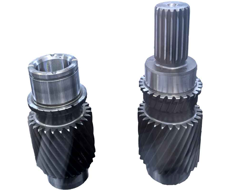
The virtual findings were corroborated by physical gear cutting experiments. A CNC gear milling machine was programmed with the calculated adjustment parameters to cut the actual spiral bevel gear pair. Subsequent to the gear cutting operations, the manufactured gears were assembled on a rolling test machine according to the specified mounting distances. The contact pattern obtained from the rolling test under light load for the gear convex side showed a well-defined, centrally located elliptical contact area. Its characteristics—shape, size, and orientation—closely matched the predictions from the virtual TCA, accounting for minor deviations due to inevitable machine errors, setup inaccuracies, and deflection. This experimental validation underscores the practical viability and robustness of the Spread-Out Helix Modified Roll gear cutting methodology in a real manufacturing context.
In conclusion, the development and analysis of the Spread-Out Helix Modified Roll method represent a significant step forward in spiral bevel gear cutting technology. By fundamentally altering the pinion cutter orientation to achieve parallelism with the gear cutter axis and incorporating a controlled helix feed motion, this method addresses the root geometrical cause of diagonal contact. The comprehensive mathematical model, based on gear meshing theory and vector analysis, provides a systematic way to calculate all necessary machine-tool settings, moving away from reliance on empirical adjustments. The successful virtual simulation and physical gear cutting experiments consistently demonstrate that this approach can effectively eliminate the detrimental diagonal contact pattern, thereby enhancing the meshing performance, load distribution, and longevity of the gear pair. Moreover, by providing a principled solution, this gear cutting technique has the potential to significantly improve manufacturing efficiency by reducing the time-consuming trial-and-error process traditionally associated with achieving a satisfactory contact pattern. Future work may involve extending this gear cutting principle to hypoid gears, optimizing the curvature modification increments for different load cases, and further integrating the method into fully automated, intelligent gear cutting systems.