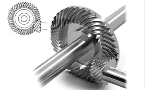
This study investigates the meshing stiffness calculation of spiral bevel gears using finite element analysis (FEA), focusing on the dynamic behavior influenced by time-varying stiffness. The methodology addresses limitations in existing approaches that approximate stiffness curves with trigonometric functions, which compromise accuracy in dynamic simulations.
1. Mathematical Formulation of Meshing Stiffness
The single-tooth meshing stiffness is defined as:
$$k_n = \frac{F_n}{u_n}$$
where \( F_n \) represents the normal contact force, and \( u_n \) denotes the comprehensive elastic deformation. For multi-tooth engagement, the total meshing stiffness becomes:
$$k_m = \sum_{i=1}^{p} k_{ni}$$
where \( p \) indicates the number of simultaneously engaged teeth.
2. Finite Element Modeling of Spiral Bevel Gears

2.1 Geometric Model Construction
Spiral bevel gear geometry is reconstructed using NURBS surface fitting based on discrete tooth profile data points. Key parameters for the analyzed gear pair include:
| Parameter | Pinion | Gear |
|---|---|---|
| Number of Teeth | 17 | 28 |
| Module (mm) | 10.357 | |
| Spiral Angle (°) | 35 | |
| Face Width (mm) | 50 | |
2.2 Finite Element Implementation
Key FEA implementation steps include:
- Mesh generation with 8-node hexahedral elements (C3D8R)
- Material properties: \( E = 209\ \text{GPa}, \nu = 0.3 \)
- Contact definition with friction coefficient \( \mu = 0.15 \)
- Boundary conditions via reference point coupling
3. Stiffness Calculation Methodology
The comprehensive deformation \( u_n \) combines Hertz contact deformation \( u_H \) and bending deformation \( u_b \):
$$u_n = \sqrt{\sum_{i=1}^{2} u_{Hi}^2 + \sum_{i=1}^{2} u_{bi}^2}$$
4. Results and Discussion
4.1 Single Tooth Stiffness Characteristics
Table 1 shows the stiffness variation during meshing:
| Rotation Angle (°) | Stiffness (MN/m) |
|---|---|
| 1 | 105.001 |
| 10 | 625.853 |
| 20 | 743.818 |
| 30 | 55.611 |
4.2 Load-Dependent Stiffness Behavior
The contact ratio \( \varepsilon \) varies with applied torque:
$$\varepsilon = \frac{\Delta T}{\Delta t}$$
where \( \Delta T \) represents engagement duration and \( \Delta t \) the phase difference between adjacent teeth.
| Torque (MN·m) | Contact Ratio |
|---|---|
| 15 | 2.524 |
| 6.5 | 2.238 |
| 0.8 | 1.650 |
4.3 Multi-Tooth Engagement Stiffness
The phase-shifted superposition method calculates total stiffness:
$$\Delta \alpha = \frac{\phi}{\varepsilon}$$
where \( \phi \) is the total meshing rotation angle.
5. Conclusion
This investigation establishes a robust FEA-based methodology for spiral bevel gear stiffness calculation, demonstrating:
- Load magnitude significantly affects stiffness amplitude (15-25% variation observed)
- Contact ratio increases by 53% when torque rises from 0.8 MN·m to 15 MN·m
- Nonlinear stiffness behavior requires consideration in dynamic modeling
The developed approach provides critical inputs for spiral bevel gear dynamic analysis, particularly in high-precision applications where traditional trigonometric approximations prove inadequate.
