
In my extensive experience within precision gear manufacturing, I have come to deeply appreciate the superior performance and high load-carrying capacity of spiral gears. These gears, primarily represented by the Klingelnberg and Gleason tooth systems, are a cornerstone of modern transmission technology. The advantages of spiral gears are multifaceted: they ensure smooth transmission with minimal noise, increased overlap ratio that reduces impact, lower specific load pressure for even wear and extended service life, the ability to achieve high transmission ratios with pinions as few as five teeth, and the possibility of finishing processes like lapping or grinding to enhance surface finish and achieve precision grades up to level 5. Among all design and manufacturing parameters, the tooth flank contact pattern stands out as critically important. It serves not merely as an indicator of individual gear quality but as a comprehensive metric reflecting the precision of the gearbox housing, the quality of assembly and adjustment, the overall stiffness of the gear set, and the installation conditions. It is the ultimate gauge of gear set quality under operational load.
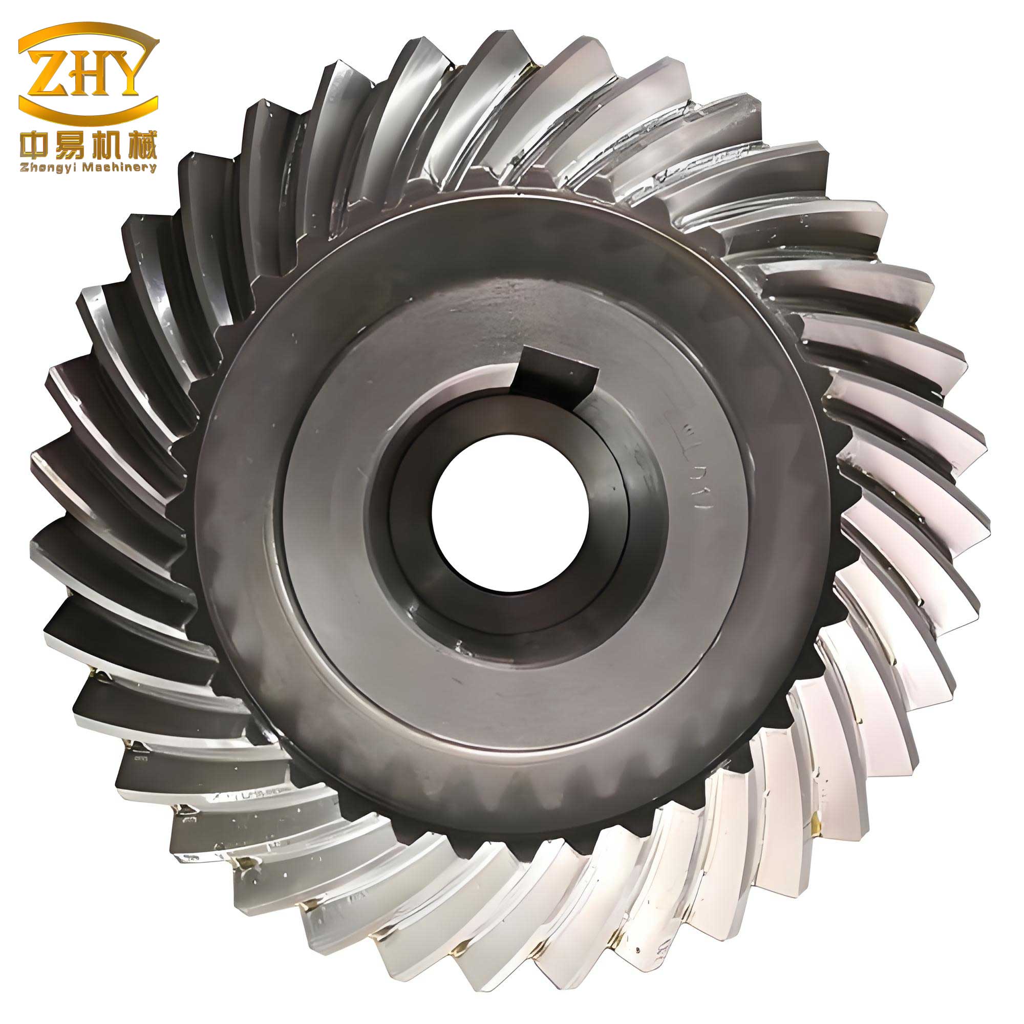
To control this vital parameter, we have developed and refined a methodology centered on reverse correction. The principle is straightforward: under load, the contact pattern on the driving flank (typically the convex side of the gear) tends to migrate toward the center and the top of the tooth. Consequently, the finished, unloaded contact pattern should be positioned slightly toward the toe and the root. The non-driving flank pattern should be biased toward the heel and top. The initial contact pattern size and position during cutting must be predetermined based on the known distortion behavior during heat treatment. In our practice, we meticulously test the contact pattern variation on a rolling tester, then use this observed规律 combined with the reverse correction principle to fine-tune the machining process until a合格 product is achieved. The study and adjustment of spiral gears contact patterns are thus fundamental to our production success.
Contact Pattern Behavior on the Rolling Tester
The position, size, and shape of the contact pattern are inspected on a rolling tester. By altering the relative installation positions of the gear pair, different contact situations can be elicited. Through countless adjustments and observations, we have systematically summarized the pattern change laws. These laws then directly inform the adjustment of machine tool parameters. The standard operational procedure is as follows: first, set the tester to the theoretical mounting distance using gauge blocks and secure the gear pair. The two axle housings are positioned according to pre-set scales. For inspection efficiency and clarity, we typically observe the contact pattern on the gear flank while using the pinion’s pattern change规律 as the basis for machine tool adjustment. Therefore, we apply a thin layer of marking compound (e.g., red lead) to the pinion teeth. After engaging the gears, we run the tester for approximately 30 seconds in each direction. The resulting印记 reveals the contact pattern location. Based on this method, the following table summarizes the change规律 for a left-hand pinion when altering the relative positions of the tester spindles.
| Adjustment Component | Contact Pattern Shift Along Tooth Height (Pinion) | Concave Flank Shift Along Tooth Length | Convex Flank Shift Along Tooth Length |
|---|---|---|---|
| Increase Mounting Distance (+ΔH) | Moves significantly from top toward root | Shifts slightly toward toe | Shifts slightly toward heel |
| Decrease Mounting Distance (-ΔH) | Moves significantly from root toward top | Shifts slightly toward heel | Shifts slightly toward toe |
| Positive Offset (+ΔV) | Moves slightly from top toward root | Shifts significantly from heel toward toe | Shifts significantly from toe toward heel |
| Negative Offset (-ΔV) | Moves slightly from root toward top | Shifts significantly from toe toward heel | Shifts significantly from heel toward toe |
Note: 1. For a right-hand gear, the pattern shift规律 is consistent, but the signs for ΔH and ΔV are opposite. 2. For a right-hand pinion, the shift规律 along the tooth length is opposite to that of a left-hand pinion, while the shift along tooth height remains the same. Understanding these规律 for spiral gears is the first step toward effective correction.
Systematic Correction of the Contact Pattern
In real production, various factors such as new product development, tool replacement after breakage, or operator changeover can cause the contact pattern to deviate from its desired location. To systematically bring it back, we employ the following methods, which are grounded in the geometry of spiral gears.
Correcting Contact Pattern Position Along the Tooth Length
The position along the tooth length is governed by the spiral angle. The slope along the tooth trace is directly related to this angle. Therefore, an error in spiral angle causes the pattern to shift toward the toe or heel. Correction is generally achieved by modifying the radial tool setting, which changes the effective spiral angle. Concurrent adjustments to horizontal and vertical workpiece positions, as well as checks on cutter blade diameter, may be necessary. The relationship can be conceptually expressed as a change in the developed spiral angle $\beta$ due to a change in radial tool distance $R$:
$$ \Delta \beta \approx -k_{\beta} \cdot \Delta R $$
where $k_{\beta}$ is a positive constant dependent on the gear geometry and machine setup. Thus, to increase the spiral angle (which would shift the pattern on a left-hand pinion concave flank toward the heel), the radial tool distance must be decreased. The magnitude of adjustment for constant-height teeth typically ranges from 0.1 to 0.6 mm, determined empirically or calculated from the ΔV value observed on the tester. The directional impact of changes for spiral gears is summarized below.
| Changed Factor | Effect on Concave Flank (Toe/Heel) | Effect on Convex Flank (Toe/Heel) |
|---|---|---|
| Decrease Radial Tool Distance or Eccentric Angle | Shifts from toe toward heel | Shifts from heel toward toe |
| Increase Radial Tool Distance or Eccentric Angle | Shifts from heel toward toe | Shifts from toe toward heel |
Correcting Contact Pattern Position Along the Tooth Height
The position along the tooth height is determined by the pressure angle. A pattern biased toward the top or root indicates a pressure angle error. Corrections often need to be combined with spiral angle adjustments. We use two primary methods for spiral gears:
- For small corrections: Modify the machine center (cradle) setting and the sliding base position. If the pattern is at the top (top contact), decrease the cradle center distance and increase the sliding base setting. For root contact, do the opposite. This alters the effective pressure角 $\alpha$:
$$ \Delta \alpha \approx k_{\alpha,1} \cdot (-\Delta E_c + \Delta X_b) $$
where $\Delta E_c$ is the cradle center change and $\Delta X_b$ is the sliding base change, with $k_{\alpha,1}$ as a proportionality factor.
- For larger corrections (2°-3°): Change the machine ratio (roll). To correct top contact on the pinion, increase the roll ratio; to correct root contact, decrease it. This relationship can be modeled as:
$$ \Delta \alpha \approx k_{\alpha,2} \cdot \Delta i $$
where $\Delta i$ is the change in machine roll ratio.
Correcting Diagonal Contact
Diagonal contact arises primarily from using the face-milling (Formate or Helixform) generating principle, where the spiral angle and pressure角 vary along the tooth length. On the convex flank, the pressure角 is smaller at the heel and larger at the toe, leading to a natural tendency for the pattern to run from the toe root to the heel top—an “inner diagonal” condition. The concave flank exhibits the opposite tendency. Incorrect nominal cutter diameter or erroneous setup data can also cause this. Mild diagonal contact may disappear during run-in. For necessary corrections, the “Roll Ratio – Horizontal Workpiece Position” method is effective, accompanied by changes to the sliding base (to maintain depth) and radial tool distance (to maintain lengthwise position). The adjustments for spiral gears are detailed below.
| Type of Diagonal Contact | Flank | Radial Tool Distance Change | Horizontal Workpiece Change | Sliding Base Change |
|---|---|---|---|---|
| Outer Diagonal | Convex | Increase | Decrease | Decrease |
| Concave | Decrease | Increase | Increase | |
| Inner Diagonal | Convex | Decrease | Increase | Increase |
| Concave | Increase | Decrease | Decrease |
Alternative methods include modifying the generating roll附加 motion or adjusting the vertical workpiece offset (hypoid offset).
Adjusting Contact Pattern Width
The width of the contact pattern, which influences the localized contact stress, is commonly adjusted by changing the vertical workpiece offset. This adjustment alters the relative curvature of the mating flanks. The effect is consistent for spiral gears, as shown in the following table. The change in pattern width $\Delta W$ can be qualitatively related to the vertical offset change $\Delta V$:
$$ \Delta W \propto |\Delta V| $$
The direction of change determines which flank is affected.
| Gear Hand | Flank | Direction of Vertical Offset Increase | Effect on Pattern Width |
|---|---|---|---|
| Left-Hand | Convex | Upward | Widens |
| Concave | Downward | Widens | |
| Right-Hand | Convex | Downward | Widens |
| Concave | Upward | Widens |
The interplay between vertical offset ($V$), radial tool distance ($R$), and machine roll ratio ($i$) for achieving a desired pattern width $W_t$ can be conceptualized through an empirical relation:
$$ W_t \approx f(V, R, i) = C_0 + C_1 \cdot V + C_2 \cdot R + C_3 \cdot i $$
where $C_0, C_1, C_2, C_3$ are coefficients determined for a specific spiral gears setup through regression analysis of production data.
Conclusion and Practical Synthesis
The adjustment methods described above for spiral gears are not applied in isolation. In practice, contact pattern deviation often requires a comprehensive adjustment involving several parameters simultaneously. For instance, correcting a pattern that is both too high and too far toward the toe on a left-hand pinion concave flank might involve decreasing the radial tool distance (to shift it heelward and increase spiral angle) while also decreasing the cradle center setting (to shift it rootward and modify pressure angle). The exact combination is derived from the规律 in Table 1 and the corrective actions in subsequent tables. Mastery of spiral gears manufacturing lies in developing an intuitive understanding of these interactions through hands-on experience. We continuously refine our approach by documenting case studies, performing statistical analysis on adjustment outcomes, and integrating feedback from performance testing. The contact pattern remains the ultimate arbiter of quality for spiral gears. By diligently applying these inspection and correction principles, we significantly increase yield rates, ensure reliable product performance, and enhance overall operational efficiency. The geometry of spiral gears is complex, but through systematic analysis and adjustment of the contact pattern, their full potential in transmitting power smoothly and reliably is consistently realized.
Further refinement of these techniques for spiral gears involves advanced simulation. The initial contact pattern under load can be modeled using Hertzian contact theory modified for crowned surfaces. The contact ellipse dimensions ($2a$ along length, $2b$ along height) and its center position ($x_c, y_c$) are functions of the machine setup parameters. A simplified analytical view considers the unloaded separation $S(x,y)$ between flanks:
$$ S(x,y) = \frac{x^2}{2R_{lx}} + \frac{y^2}{2R_{ly}} + \delta_0 + \theta_x \cdot x + \theta_y \cdot y $$
where $R_{lx}$ and $R_{ly}$ are the relative principal radii of curvature along length and height, $\delta_0$ is the approach distance, and $\theta_x$, $\theta_y$ are misalignment angles. The machine adjustments (ΔV, ΔH, ΔR, etc.) directly influence these curvature radii and misalignments. For example, changing the vertical offset ΔV primarily alters $R_{ly}$ and $\theta_y$. The loaded contact pattern corresponds to the region where $S(x,y) \leq \delta$, with $\delta$ being the elastic deformation. Optimizing the setup is essentially about preshaping $S(x,y)$ so that under load, the contact ellipse is centered and sized correctly. This mathematical framework, though simplified, guides our understanding of how subtle changes in spiral gears machining parameters propagate to final performance.
In closing, the journey of perfecting spiral gears is one of perpetual learning. Each new gear set presents a unique puzzle where the contact pattern is the key. By combining rigorous empirical规律 with evolving theoretical models, we continue to push the boundaries of precision and reliability in spiral gears transmission systems. The methods outlined here, born from extensive production experience, provide a robust foundation for anyone engaged in the manufacture or application of these remarkable mechanical components.