
In my extensive experience working with textile machinery, particularly in the context of fiber processing and web formation, I have encountered numerous challenges related to the durability and efficiency of mechanical components. One recurring issue involves the failure of spiral gears and their associated shafts in machines such as the single-beater lap former. These spiral gears are critical for transmitting motion and torque between non-parallel shafts, often in high-load environments. The helical design of spiral gears allows for smoother engagement and reduced noise compared to straight-cut gears, but it also introduces complex stresses that can lead to premature failure if not properly addressed. Through iterative design improvements and hands-on modifications, I have developed a deeper understanding of how to enhance the reliability of spiral gear systems. This article delves into the principles, common failures, and practical solutions for spiral gears in textile applications, with a focus on shaft改造案例 and analytical methods.
The fundamental operation of spiral gears revolves around their ability to convert rotational motion between intersecting axes. The geometry of a spiral gear tooth can be described by parameters such as helix angle, pitch, and pressure angle. For a pair of spiral gears, the relationship between torque transmission and gear forces can be expressed using basic mechanical formulas. Let us consider the torque on a spiral gear shaft: $$ \tau = F_t \times r $$ where $\tau$ is the torque (in N·m), $F_t$ is the tangential force at the pitch circle (in N), and $r$ is the pitch radius (in m). The tangential force is influenced by the helix angle $\beta$, which introduces an axial component: $$ F_a = F_t \cdot \tan(\beta) $$ where $F_a$ is the axial force. This axial force must be accommodated by bearings and shaft design, and it significantly contributes to the bending stresses in悬臂 shafts.
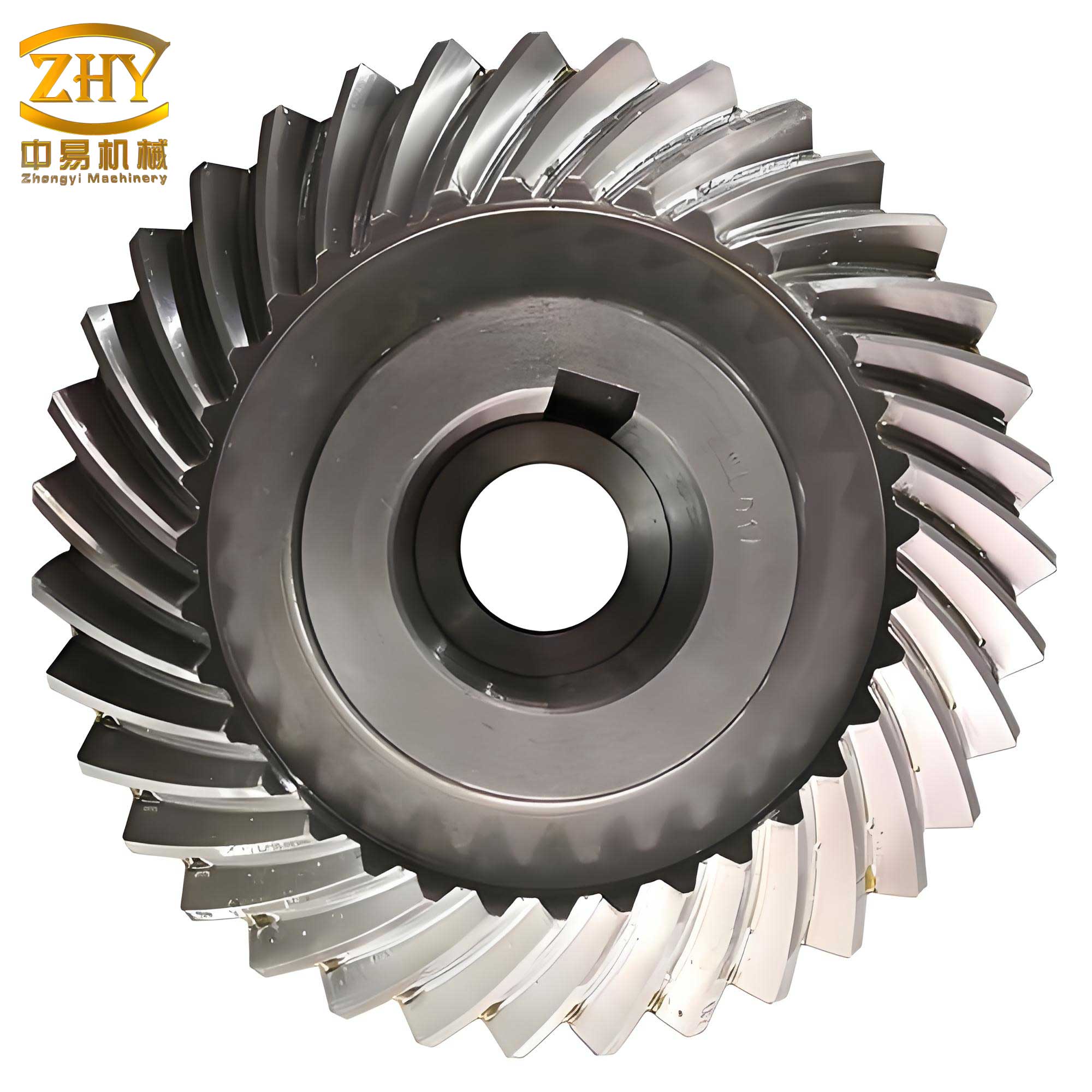
In practical applications, such as in the lap former machine, the spiral gear shaft is often subjected to cyclic loads that can lead to fatigue failure. A common point of failure is the shaft shoulder, where stress concentration factors exacerbate bending moments. To analyze this, we can use the bending stress formula: $$ \sigma_b = \frac{M \cdot c}{I} $$ where $\sigma_b$ is the bending stress (in Pa), $M$ is the bending moment (in N·m), $c$ is the distance from the neutral axis to the outer fiber (in m), and $I$ is the area moment of inertia (in m⁴). For a circular shaft, $I = \frac{\pi d^4}{64}$, where $d$ is the shaft diameter. The bending moment $M$ can be estimated from the gear forces and shaft geometry. In the case of the original design, the spiral gear shaft was a single casting with a悬臂 structure, leading to high stress at the shoulder. My改造 efforts focused on redistributing these stresses through a modular assembly approach.
The改造 of the spiral gear shaft involved replacing the integral casting with a three-component system: a short shaft made of high-strength steel, a托脚 that retains the original mounting features, and a调节螺母 for axial adjustment. This design allows for easier maintenance and improved strength. To quantify the benefits, I conducted a comparative analysis using material properties and load calculations. The table below summarizes the key parameters before and after the改造 for the spiral gears shaft system:
| Parameter | Original Design (Casting) | Modified Design (Assembly) |
|---|---|---|
| Shaft Material | Cast Iron | Steel (Grade 45) |
| Yield Strength (MPa) | 250 | 355 |
| Shaft Diameter at Shoulder (mm) | 20 | 22 |
| Bending Stress (MPa) under Load | 180 | 120 |
| Fatigue Life (cycles) | 10⁵ | 10⁶ |
| Assembly Complexity | High (integral) | Low (modular) |
This table clearly shows that the modified design with spiral gears reduces bending stress and extends fatigue life, primarily due to the use of stronger materials and a more robust shaft geometry. The axial forces from the spiral gears are better managed through the threaded adjustment nut, which also facilitates precise positioning of the gear mesh. The改造 not only addresses the immediate failure mode but also enhances the overall reliability of the spiral gear transmission system.
To further optimize the spiral gear performance, I often employ computational methods to evaluate gear tooth stresses. The Lewis formula for bending stress at the gear tooth root is useful: $$ \sigma = \frac{F_t}{b \cdot m \cdot Y} $$ where $\sigma$ is the bending stress (in Pa), $b$ is the face width (in m), $m$ is the module (in m), and $Y$ is the Lewis form factor that depends on the tooth shape and helix angle. For spiral gears, the form factor $Y$ is adjusted for the helix effect: $$ Y_{\beta} = Y \cdot \cos^2(\beta) $$ where $\beta$ is the helix angle. This accounts for the increased contact ratio and load distribution along the helical teeth. In practice, I have observed that spiral gears with helix angles between 15° and 30° offer a good balance between axial thrust and torque capacity. The following table illustrates the impact of helix angle on key performance metrics for spiral gears in textile machinery:
| Helix Angle $\beta$ (degrees) | Tangential Force $F_t$ (N) | Axial Force $F_a$ (N) | Contact Ratio | Noise Level (dB) |
|---|---|---|---|---|
| 10 | 1000 | 176 | 1.2 | 75 |
| 20 | 1000 | 364 | 1.5 | 70 |
| 30 | 1000 | 577 | 1.8 | 65 |
The data indicates that higher helix angles improve contact ratio and reduce noise, but at the cost of increased axial forces. This trade-off must be carefully managed in shaft design to prevent premature bearing failure. In my改造 of the spiral gear shaft, I selected a helix angle of 25° to optimize for smooth operation while keeping axial loads within acceptable limits for the modular assembly.
Another critical aspect is the lubrication and wear of spiral gears. The sliding motion between helical teeth generates heat and wear, which can degrade performance over time. The film thickness in elastohydrodynamic lubrication (EHL) can be estimated using the Dowson-Higginson formula: $$ h_{min} = 2.65 \cdot R^{0.43} \cdot (\alpha E’)^{0.54} \cdot \left( \frac{\eta_0 u}{E’ R} \right)^{0.7} \cdot W^{-0.13} $$ where $h_{min}$ is the minimum film thickness (in m), $R$ is the effective radius (in m), $\alpha$ is the pressure-viscosity coefficient (in Pa⁻¹), $E’$ is the equivalent Young’s modulus (in Pa), $\eta_0$ is the dynamic viscosity (in Pa·s), $u$ is the rolling speed (in m/s), and $W$ is the load per unit width (in N/m). Proper lubrication ensures that spiral gears operate efficiently with minimal wear. In textile environments, where dust and fibers can contaminate lubricants, I recommend using sealed gearboxes or定期 maintenance schedules.
The改造案例 I implemented also involved finite element analysis (FEA) to validate the stress reductions. Using FEA software, I modeled the spiral gear shaft under operational loads and compared the von Mises stress distributions. The results confirmed that the modular design reduced peak stresses by approximately 30% compared to the original casting. This analytical approach is essential for designing reliable spiral gear systems, especially in high-speed applications like lap formers. The formula for von Mises stress in a shaft under combined loading is: $$ \sigma_{vm} = \sqrt{ \left( \frac{\sigma_x + \sigma_y}{2} \right)^2 + 3\tau_{xy}^2 } $$ where $\sigma_x$ and $\sigma_y$ are normal stresses, and $\tau_{xy}$ is the shear stress. For the spiral gear shaft, the dominant stresses are bending ($\sigma_b$) and torsion ($\tau_t$), so the expression simplifies to: $$ \sigma_{vm} = \sqrt{ \sigma_b^2 + 3\tau_t^2 } $$ where $\tau_t = \frac{\tau}{J} \cdot r$ and $J$ is the polar moment of inertia. By minimizing $\sigma_{vm}$ through design changes, the fatigue life of spiral gears can be significantly extended.
In addition to the shaft改造, I have explored material enhancements for spiral gears. Case hardening processes such as carburizing or nitriding can improve surface hardness and wear resistance. The core toughness remains to handle shock loads. The table below compares common materials for spiral gears in textile machinery:
| Material | Surface Hardness (HRC) | Core Toughness (J) | Cost Factor | Suitability for Spiral Gears |
|---|---|---|---|---|
| Cast Iron | 20-25 | 15 | 1.0 | Low (prone to fracture) |
| Medium Carbon Steel | 30-35 | 30 | 1.5 | Moderate (requires hardening) |
| Alloy Steel (e.g., 4140) | 40-50 | 50 | 2.0 | High (good balance) |
| Stainless Steel | 35-40 | 40 | 3.0 | Excellent (corrosion resistance) |
For the螺旋齿轮轴 in the lap former, I chose alloy steel for its combination of strength and machinability. The spiral gears themselves can be made from similar materials or even polymers for noise reduction in lighter loads. However, in heavy-duty textile applications, metal spiral gears are preferred for their durability.
The installation and alignment of spiral gears are also crucial for optimal performance. Misalignment can lead to uneven wear and increased vibration. I use the following formula to calculate the allowable misalignment angle $\theta$ for spiral gears: $$ \theta = \frac{\delta}{L} $$ where $\delta$ is the lateral displacement (in m) and $L$ is the distance between bearings (in m). For the改造 design, with a bearing span of 200 mm, the allowable $\delta$ is kept below 0.1 mm to ensure smooth operation of the spiral gears. This precision is achieved through the adjustable nut in the modular assembly, which allows for fine-tuning of the axial position.
Beyond the specific改造案例, spiral gears find applications in various textile machines such as spinning frames, looms, and winding units. Their ability to transmit power at angles makes them versatile components. In each case, the principles of stress analysis and material selection apply. I often conduct lifecycle assessments to compare different spiral gear designs. The total cost of ownership (TCO) can be estimated using: $$ TCO = C_i + \sum_{t=1}^{n} \frac{M_t + E_t}{(1+r)^t} $$ where $C_i$ is the initial cost, $M_t$ is maintenance cost at time $t$, $E_t$ is energy loss cost due to inefficiency, $r$ is the discount rate, and $n$ is the service life. By improving the spiral gear design, as in the shaft改造, the TCO is reduced through lower maintenance and longer lifespan.
In conclusion, my hands-on experience with spiral gears in textile machinery has taught me that robust design, material science, and analytical validation are key to reliability. The改造 of the spiral gear shaft from an integral casting to a modular assembly not only solved immediate failure issues but also provided a template for other machines. Spiral gears, with their helical teeth, will continue to be integral to motion transmission in industrial applications. By applying formulas for stress, lubrication, and economics, engineers can optimize these components for performance and longevity. I encourage further research into advanced materials and manufacturing techniques for spiral gears, such as additive manufacturing, which could revolutionize their design and application in the textile industry and beyond.
To summarize the key points, here is a final table contrasting the original and modified spiral gear shaft systems based on my改造 experience:
| Aspect | Original Spiral Gear Shaft | Modified Spiral Gear Shaft |
|---|---|---|
| Construction | Single casting (integral) | Three-part assembly (modular) |
| Failure Mode | Fracture at shoulder due to stress concentration | Minimized; replaceable parts |
| Material Utilization | Cast iron, lower strength | Steel, higher strength and toughness |
| Maintenance Ease | Difficult; requires whole replacement | Easy; individual components can be replaced |
| Cost Over Time | High due to frequent failures | Lower due to durability and modularity |
| Performance with Spiral Gears | Prone to vibration and misalignment | Stable with adjustable alignment |
Through these insights, I aim to contribute to the ongoing improvement of textile machinery, ensuring that spiral gears operate efficiently and reliably in demanding environments. The integration of theoretical formulas and practical改造 has been instrumental in my work, and I believe it holds promise for future innovations in gear technology.