
It can be seen from the research that the change of finishing forming force is not only affected by the size of finishing quantity, but also related to the obstruction of die cavity. Therefore, according to the tooth shape structure of the spiral bevel gear, the tooth root circle of the tooth shape cavity of the female die is expanded to make the spiral bevel gear tooth shape blank flow freely at the tooth top in the cold finishing process, so as to reduce the forming force and improve the service life of the die. However, the tooth top of the spiral bevel gear can be completed only by subsequent simple machining.
Figure 1 shows the flow direction of metal material at each point at the end of forming. 4.10-a shows the metal flow direction when the tooth root circle of the tooth cavity of the female die is not expanded. By observing the metal flow velocity at the tooth shape of the spiral bevel gear, it can be seen that the flow velocity on the tooth surface of the spiral bevel gear is greater than that at the tooth top, and the maximum flow velocity is 28.3mm/s; Figure B shows the metal flow speed after the tooth root circle of the tooth cavity of the female die is expanded. Compared with figure a, it can be found that due to the unconstrained reason at the tooth top of the spiral bevel gear, at the end of the forming, the metal material at the tooth shape of the spiral bevel gear continues to flow towards the tooth cavity of the female die. The metal flow speed at each point at the tooth top of the spiral bevel gear is more intense than that in figure a, and the maximum flow speed is 36mm / s.
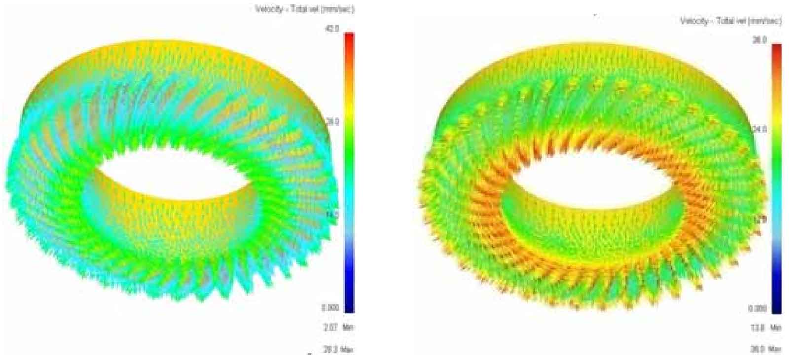
Figure 2 shows the corresponding stroke load relationship curve with or without addendum constraint. The dotted line and solid line are the stroke load curves with and without addendum constraint respectively. It can be seen from the curve that the stroke load curves of the two schemes tend to coincide in the early stage of cold finishing of spiral bevel gear tooth profile, which is mainly the gradual combination of preform tooth profile and die cavity; In the middle stage of forming, the travel load curve (dotted line) of the constrained top of the spiral bevel gear rises sharply, while the unconstrained travel load curve (solid line) of the top of the spiral bevel gear rises slowly, because when the top of the tooth is unconstrained, the top of the spiral bevel gear plays a role of diversion. At the end of forming, according to the different structure of the die, the excess metal materials continue to flow along their respective directions. At this time, the forming force increases steadily until the final stroke is reached, and the tooth profile finishing of spiral bevel gear is completed.
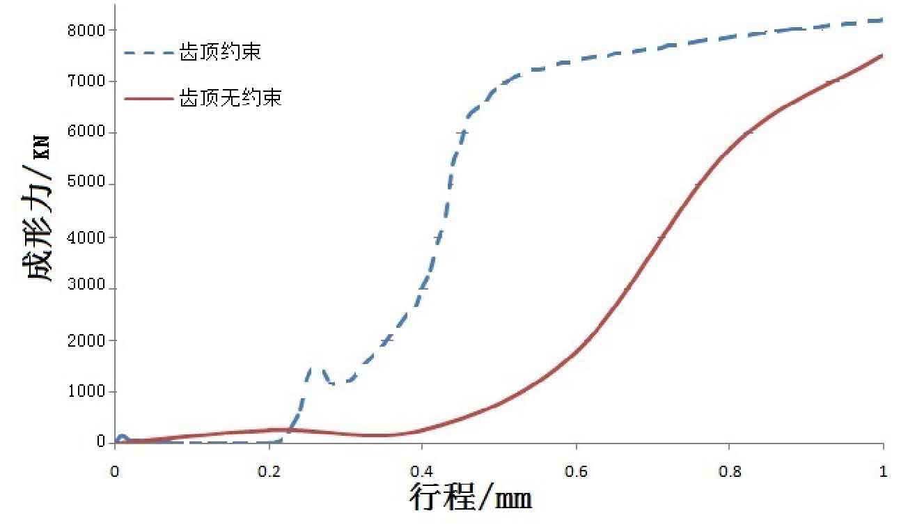
By observing the stroke load relationship curve in Figure 2, it can be seen that when the crown of the spiral bevel gear is constrained, the forming force at the end of the tooth profile finishing of the spiral bevel gear is 8220kn, while when the crown is not constrained, the forming force is 7530kn, which is reduced by 8.39%. When cold finishing the tooth profile, the most stressed part is the tooth profile of the female die. Excessive forming force is easy to cause the collapse of the tooth profile of the spiral bevel gear and reduce the service life of the die. Therefore, it is necessary to put forward the unconstrained cold finishing scheme of the tooth top of the spiral bevel gear. In order to reduce the forming force, the scheme has a certain reference value.