
In the field of mechanical transmission, spiral bevel gears play a critical role in transferring power between intersecting axes, widely employed in automotive, aerospace, and marine industries. However, traditional manufacturing methods for spiral bevel gears often lead to undesirable tooth contact patterns, such as bias contact or diagonal contact, which can compromise meshing performance and reduce gear life. To address this issue, I propose a novel machining approach called the spread-out helix modified roll. This method involves generating the gear (larger wheel) using conventional generating techniques while machining the pinion (smaller wheel) with a helix-modified roll process. In this article, I will delve into the principles behind this method, establish geometric models, derive tooth surface equations, perform tooth contact analysis (TCA), and present simulation and experimental results. The focus is on eliminating diagonal contact theoretically and improving the quality of tooth contact for spiral bevel gears.
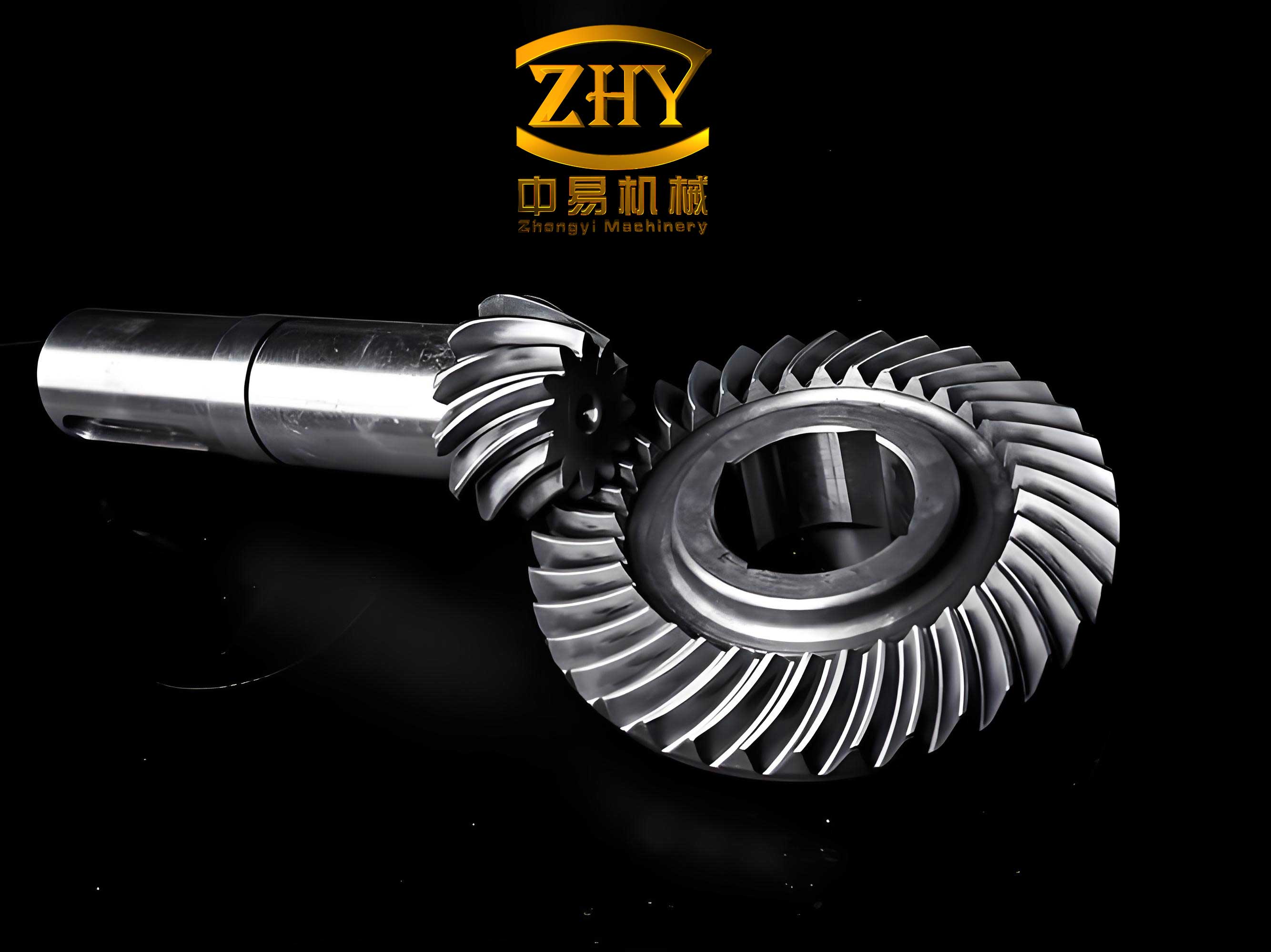
The spiral bevel gear is a complex component due to its curved teeth and varying geometry along the tooth profile. Traditional generating methods for spiral bevel gears involve positioning the cutter axis perpendicular to the root cone of the gear being machined. While this approach is standard, it inherently causes a mismatch in pressure angles along the tooth length, leading to diagonal contact. This phenomenon occurs because the pressure angles at points other than the midpoint of the tooth line are not equal between mating gears. The spread-out helix modified roll aims to correct this by altering the cutter orientation for the pinion, aligning the cutter axis perpendicular to the face cone instead of the root cone. This adjustment ensures that the pressure angles of the pinion and gear correspond correctly, thereby eliminating diagonal contact from a theoretical standpoint.
To understand the spread-out helix modified roll, it is essential to analyze the geometry of spiral bevel gears and the cutting process. I will begin by examining the traditional generating method and its limitations. Then, I will introduce the new method, detailing the geometric relationships and deriving the necessary equations. The tooth surface generation involves complex kinematics of machine tools, cutter motion, and coordinate transformations. I will establish mathematical models for both the pinion and gear tooth surfaces, incorporating the spread-out helix modified roll parameters. Subsequently, I will perform tooth contact analysis to predict the contact pattern and transmission error. Finally, I will present simulation results and experimental validation, comparing the new method with traditional approaches. Throughout this discussion, the term ‘spiral bevel gear’ will be emphasized to highlight the application context.
1. Introduction to Spiral Bevel Gears and Diagonal Contact
Spiral bevel gears are widely used in applications requiring high torque and smooth operation at intersecting shafts. Their teeth are curved and oblique, which allows for gradual engagement and reduced noise compared to straight bevel gears. However, the manufacturing of spiral bevel gears is challenging due to the need for precise tooth geometry to ensure proper meshing. Traditional generating methods, such as those developed by Gleason, have been industry standards for decades. In these methods, the cutter axis is set perpendicular to the root cone of the workpiece. While this simplifies setup, it leads to an inherent issue: the pressure angles along the tooth line vary, causing the contact area to shift diagonally across the tooth face. This diagonal contact can result in stress concentrations, increased wear, and reduced efficiency.
The diagonal contact problem arises from the geometry of the spiral bevel gear. In traditional generating, the cutter pressure angle at the root cone is constant, but when projected onto the pitch cone, it changes due to the spiral angle. Specifically, for a point at a distance x from the midpoint along the tooth line, the spiral angle β_x differs from the nominal spiral angle β. This causes the pressure angles on the pinion and gear to mismatch except at the midpoint. The spread-out helix modified roll addresses this by adjusting the cutter orientation for the pinion so that the pressure angles match along the entire tooth line. This method is inspired by earlier works such as the helix-form method and spread-out helix techniques, but it combines generating for the gear and helix-modified roll for the pinion in a unique way.
2. Principle of Spread-Out Helix Modified Roll
The spread-out helix modified roll method involves two key steps: the gear is machined using conventional generating with the cutter axis perpendicular to its root cone, while the pinion is machined with a helix-modified roll where the cutter axis is perpendicular to its face cone. This ensures that the cutter surfaces for both members are conformal, leading to matched pressure angles. To illustrate, consider the geometry of the pinion cutter installation. In traditional generating, the cutter axis is perpendicular to the root cone, leading to pressure angles on the pitch cone given by:
$$ \alpha_{i1} = \alpha – \Delta \alpha_1 $$
$$ \alpha_{a1} = \alpha + \Delta \alpha_1 $$
where Δα₁ = θ_f1 sin β, with θ_f1 being the root angle of the pinion and β the spiral angle. For the gear, similar equations apply with Δα₂ = θ_f2 sin β. Since θ_f1 and θ_f2 are typically not equal, the pressure angles mismatch, causing diagonal contact.
In the spread-out helix modified roll for the pinion, the cutter axis is perpendicular to the face cone. This changes the pressure angles on the pitch cone to:
$$ \alpha’_{i1} = \alpha + \Delta \alpha’_1 $$
$$ \alpha’_{a1} = \alpha – \Delta \alpha’_1 $$
where Δα’₁ = θ_a1 sin β, with θ_a1 being the face angle of the pinion. For the gear, the pressure angles remain as before. However, in a spiral bevel gear set, the face angle of the pinion equals the root angle of the gear (θ_a1 = θ_f2) due to the gear geometry. Therefore, Δα’₁ = Δα₂, ensuring that α’_{a1} = α_{i2} and α’_{i1} = α_{a2}. This means the pressure angles of the pinion and gear are equal for the convex and concave surfaces, respectively, eliminating the diagonal contact theoretically.
The helix-modified roll process for the pinion involves an additional helical motion during cutting, where the cutter moves along a spiral path. This generates an Archimedean spiral surface on the tooth, which compensates for the pressure angle variation. The machine tool settings include a helical feed parameter p, which controls the spiral motion. The combination of this motion with the generating roll ensures that the tooth surface is properly formed with matched pressure angles.
3. Geometric Modeling and Tooth Surface Equations
To analyze the tooth contact of spiral bevel gears manufactured by the spread-out helix modified roll, I establish mathematical models for the tooth surfaces. This involves defining coordinate systems, cutter geometry, machine kinematics, and the envelope condition for surface generation.
3.1 Coordinate Systems and Cutter Geometry
I define several coordinate systems to describe the motion of the cutter and workpiece. Let S_t be the cutter coordinate system attached to the cutter head center, with the x_t-y_t plane representing the cutter face and z_t axis perpendicular to it. The cutter rotates about the z_t axis with angle θ_1. A coordinate system S_d is introduced that rotates with the cutter. The cutting edge is defined in a local coordinate system S_b attached to the cutting point. The position vector of a point on the cutting edge in S_b is:
$$ \mathbf{r}_{b1}(u_1) = [x_{b1}, y_{b1}, z_{b1}]^T $$
where u_1 is a parameter along the cutting edge. For a straight-edged cutter, this can be expressed as:
$$ \mathbf{r}_{b1}(u_1) = \begin{bmatrix} \pm \left( \frac{W_1}{2} + u_1 \sin \alpha \right) \\ 0 \\ -u_1 \cos \alpha \end{bmatrix} $$
where W_1 is the blade edge width, α is the cutter pressure angle, and the ± sign indicates the inner and outer blades. However, for the spread-out helix modified roll, the cutter motion includes a helical feed, so the cutting surface becomes an Archimedean spiral. In S_d, the point is transformed as:
$$ \mathbf{r}_{d1}(u_1, \theta_1) = \mathbf{M}_{dt}(\theta_1) \mathbf{M}_{tb} \mathbf{r}_{b1}(u_1) $$
where M are transformation matrices. Considering the helical motion with parameter p, the equation in S_d becomes:
$$ \mathbf{r}_{d1}(u_1, \theta_1) = \begin{bmatrix} \left( r_{c1} \pm \frac{W_1}{2} + u_1 \sin \alpha \right) \sin \theta_1 \\ \left( r_{c1} \pm \frac{W_1}{2} + u_1 \sin \alpha \right) \cos \theta_1 \\ -u_1 \cos \alpha + p \theta_1 \end{bmatrix} $$
Here, r_c1 is the cutter radius, and p is the helical feed per radian of cutter rotation.
3.2 Machine Tool Kinematics and Generation of Pinion Tooth Surface
The machine tool for spiral bevel gears includes a cradle that rotates to simulate the generating motion. I define a machine coordinate system S_m fixed to the machine center. The cutter is mounted on the cradle, which rotates about the z_m axis with angle φ_1. The cradle has a radial setting s_1 and angular setting q_1. The workpiece (pinion) is installed on the machine with settings such as sliding base distance X_B1, machine root angle δ_a1, offset X_1, and rotation angle ψ_1. The coordinate transformations from S_d to S_m and then to the workpiece system S_w are performed to obtain the tooth surface equation.
The transformation from S_d to S_m involves:
$$ \mathbf{r}_{m1}(u_1, \theta_1, \phi_1) = \mathbf{M}_{mc}(\phi_1) \mathbf{M}_{cd}(s_1, q_1) \mathbf{r}_{d1}(u_1, \theta_1) $$
Then, to S_w:
$$ \mathbf{r}_{w1}(u_1, \theta_1, \phi_1, \psi_1) = \mathbf{M}_{wh}(\psi_1) \mathbf{M}_{hr}(X_1) \mathbf{M}_{rs}(\delta_{a1}) \mathbf{M}_{sm}(X_{B1}) \mathbf{r}_{m1}(u_1, \theta_1, \phi_1) $$
The tooth surface is generated as the envelope of the cutter surface relative to the workpiece motion. The meshing condition is given by:
$$ f_1(u_1, \theta_1, \phi_1) = \mathbf{n}_{w1} \cdot \mathbf{v}_{w1}^{(12)} = 0 $$
where n_w1 is the normal vector of the cutter surface in S_w, and v_w1^{(12)} is the relative velocity between the cutter and workpiece. The normal vector is computed as:
$$ \mathbf{n}_{w1} = \frac{\partial \mathbf{r}_{w1}}{\partial u_1} \times \frac{\partial \mathbf{r}_{w1}}{\partial \theta_1} $$
and the relative velocity is derived from the kinematics. Solving the meshing condition along with the tooth surface equation yields the pinion tooth surface as a function of parameters:
$$ \mathbf{r}_1 = \mathbf{r}_1(\phi_1, \theta_1) $$
3.3 Gear Tooth Surface Equation
The gear is generated using the traditional method without helical motion. Therefore, its tooth surface equation can be derived similarly but with p = 0 and appropriate machine settings. The cutter axis is perpendicular to the gear root cone. The gear tooth surface in its coordinate system S_2 is:
$$ \mathbf{r}_2 = \mathbf{r}_2(\phi_2, \theta_2) $$
where φ_2 and θ_2 are the generation motion parameters for the gear.
4. Tooth Contact Analysis (TCA)
Tooth contact analysis is performed to predict the contact pattern and transmission error of the spiral bevel gear pair. I consider the gear pair in mesh under load-free conditions. The pinion and gear are assembled with their axes intersecting at an angle Σ. Coordinate systems are attached to each gear and a fixed assembly system S_a.
The position vectors and normal vectors of the tooth surfaces are transformed into S_a:
$$ \mathbf{r}_{a1}(\phi_1, \theta_1, \varphi_1) = \mathbf{M}_{a1}(\varphi_1) \mathbf{r}_1(\phi_1, \theta_1) $$
$$ \mathbf{n}_{a1}(\phi_1, \theta_1, \varphi_1) = \mathbf{K}_{a1}(\varphi_1) \mathbf{n}_1(\phi_1, \theta_1) $$
and similarly for the gear:
$$ \mathbf{r}_{a2}(\phi_2, \theta_2, \varphi_2) = \mathbf{M}_{a2}(\varphi_2) \mathbf{r}_2(\phi_2, \theta_2) $$
$$ \mathbf{n}_{a2}(\phi_2, \theta_2, \varphi_2) = \mathbf{K}_{a2}(\varphi_2) \mathbf{n}_2(\phi_2, \theta_2) $$
where φ_1 and φ_2 are rotation angles of pinion and gear, and M and K are transformation matrices.
The contact condition requires that at any point of contact, the position vectors coincide and the normal vectors are collinear:
$$ \mathbf{r}_{a1} = \mathbf{r}_{a2} + \mathbf{O}_1\mathbf{O}_2 $$
$$ \mathbf{n}_{a1} = \mathbf{n}_{a2} $$
where O_1O_2 is the vector between the origins. Since the normal vectors are unit vectors, the second equation gives two independent scalar equations. Thus, we have five independent equations from the vector equations. The unknowns are φ_1, φ_2, ϕ_1, θ_1, ϕ_2, θ_2 — six variables. By choosing one variable, say φ_2, as the input, we can solve for the others along the contact path.
The transmission error is computed as:
$$ \Delta \epsilon(\varphi_2) = \varphi_1(\varphi_2) – \varphi_{10} – \frac{z_2}{z_1} (\varphi_2 – \varphi_{20}) $$
where z_1 and z_2 are tooth numbers, and φ_{10}, φ_{20} are initial angles at a reference contact point.
Solving the TCA equations numerically yields the contact points on the tooth surface, which can be plotted to show the contact pattern. The spread-out helix modified roll should result in a contact pattern aligned along the tooth length without diagonal bias.
5. Simulation and Experimental Verification
I performed tooth contact analysis for a spiral bevel gear pair using both traditional generating and spread-out helix modified roll methods. The gear parameters are listed in Table 1.
| Component | Shaft Angle Σ (°) | Tooth Number z | Normal Module m (mm) | Spiral Angle β (°) | Outer Cone Distance R_e (mm) | Face Width B (mm) | Face Angle δ_a (°) | Pitch Angle δ (°) | Root Angle δ_f (°) |
|---|---|---|---|---|---|---|---|---|---|
| Pinion (concave) | 90 | 11 | 6.5 | 35 | 116.1392 | 35 | 22.3683 | 17.9276 | 15.7220 |
| Gear (convex) | 90 | 34 | 6.5 | 35 | 116.1392 | 35 | 74.2783 | 72.0724 | 67.2238 |
The machine settings for the pinion and gear are shown in Table 2.
| Component | Cutter Radius r_c (mm) | Inner Blade Angle α_i (°) | Outer Blade Angle α_a (°) | Angular Setting q (°) | Radial Setting s (mm) | Sliding Base X_B (mm) | Offset X (mm) | Machine Root Angle (°) | Ratio i | Helical Feed p (mm/rad) |
|---|---|---|---|---|---|---|---|---|---|---|
| Pinion | 114.3 | 18.75 | 21.25 | 33.98 | 88.48 | 0.3500 | 13.45 | 22.37 | 3.2453 | 0.2792 |
| Gear | 114.3 | 18.75 | 21.25 | 34.11 | 88.65 | 0.0045 | 0 | 67.22 | 1.0473 | 0 |
The TCA results for the traditional method show contact points distributed along a diagonal path. The coordinates of contact points along the tooth length (x) and height (y) are given in Table 3.
| Contact Point No. | Traditional Method x (mm) | Traditional Method y (mm) | Spread-Out Helix Modified Roll x (mm) | Spread-Out Helix Modified Roll y (mm) |
|---|---|---|---|---|
| 1 | -2.5515 | 3.0754 | -2.1557 | 3.3097 |
| 2 | -1.8187 | 3.3571 | -1.0181 | 3.7263 |
| 3 | -0.8406 | 4.5483 | -0.5148 | 4.4160 |
| 4 | 0 | 5.1193 | 0 | 5.1193 |
| 5 | -0.8021 | 5.8878 | -0.3301 | 5.8716 |
| 6 | -1.7935 | 6.7065 | -0.5088 | 6.6962 |
| 7 | -2.4231 | 7.6477 | -0.6809 | 7.6787 |
| Range | 4.9746 | 4.5723 | 2.8366 | 4.3690 |
For the traditional method, the x-range is 4.9746 mm, indicating a significant diagonal spread. In contrast, the spread-out helix modified roll yields an x-range of only 2.8366 mm, showing a more aligned contact pattern. The y-ranges are similar, but the reduced x-range demonstrates that the diagonal bias is minimized.
The contact patterns and transmission errors from TCA simulations are illustrated in Figure 1 (not shown, but described). For the traditional method, the contact path is diagonal across the tooth face, and the transmission error curve has a larger amplitude. For the spread-out helix modified roll, the contact path is more centralized along the tooth length, and the transmission error curve has a smaller amplitude with intersections, indicating no edge contact.
To validate the method, I conducted experimental cutting of a spiral bevel gear pair using the spread-out helix modified roll parameters. The gears were machined on a Gleason hypoid generator and tested on a rolling tester. The contact pattern on the gear convex side showed a well-defined, centralized area without diagonal bias, confirming the theoretical predictions. The spiral bevel gear pair exhibited smooth meshing and low noise in operation.
6. Discussion on Spiral Bevel Gear Design and Manufacturing
The spread-out helix modified roll method offers a significant improvement in the manufacturing of spiral bevel gears. By aligning the cutter axis with the face cone for the pinion, the pressure angles are matched, eliminating diagonal contact. This method is particularly beneficial for high-precision applications where tooth contact quality is critical. However, it requires careful calculation of machine settings and helical feed parameters. The geometric model presented here provides a foundation for such calculations.
Further considerations include the impact of load on tooth contact. Under load, the tooth deflections may alter the contact pattern. Therefore, loaded tooth contact analysis (LTCA) should be performed to ensure performance under operating conditions. Additionally, the spread-out helix modified roll may be combined with other modifications, such as flank corrections or ease-off topographies, to optimize the contact pattern for specific applications.
The spiral bevel gear is a complex component, and its design involves multiple parameters: spiral angle, pressure angle, tooth profile, and machine settings. The spread-out helix modified roll adds a degree of freedom with the helical feed, allowing for better control over the tooth surface geometry. This method can be implemented on modern CNC gear cutting machines, which offer the flexibility to program complex motions.
7. Conclusion
In this article, I have presented the spread-out helix modified roll method for machining spiral bevel gears. The method addresses the diagonal contact problem inherent in traditional generating by adjusting the cutter orientation for the pinion. Geometric models were developed to derive the pressure angle relationships and tooth surface equations. Tooth contact analysis showed that the spread-out helix modified roll results in a more centralized contact pattern and reduced transmission error compared to traditional methods. Experimental cutting confirmed the effectiveness, with the spiral bevel gear pair exhibiting improved contact quality. This method enhances the performance and longevity of spiral bevel gears, making it valuable for advanced gear manufacturing.
Future work may include extending the method to hypoid gears, optimizing the helical feed parameters, and integrating with digital twin simulations for virtual prototyping. The spiral bevel gear remains a key component in power transmission, and continuous improvement in manufacturing methods is essential for advancing mechanical systems.