
In the realm of mechanical engineering, the accurate measurement and calculation of spur and pinion gears are paramount for ensuring the reliability and efficiency of传动 systems. As an engineer with extensive field experience, I have encountered numerous scenarios where the need to reverse-engineer or verify the design parameters of spur and pinion gears arises, particularly in the maintenance of imported machinery. This article delves into the systematic approach for plotting and calculating spur and pinion gears, emphasizing the use of practical methods such as公法线 measurement,模数 determination, and变位系数 computation. The focus will be on spur and pinion gears, as they are fundamental components in many industrial applications, from automotive differentials to mining equipment. Throughout this discussion, the keywords ‘spur and pinion’ will be frequently highlighted to underscore their significance in gear metrology.
The process of spur and pinion gear metrology involves deriving original design parameters—such as模数 (m) or径节 (DP),齿形角 (α),螺旋角 (β), and变位系数 (x)—from physical measurements. This is essentially akin to redesigning the spur and pinion gear from scratch, requiring a solid foundation in gear theory. For spur gears, which are cylindrical gears with straight teeth, the测绘 is relatively straightforward compared to helical or bevel gears, but it still demands precision. The pinion, often the smaller gear in a pair, must be carefully analyzed alongside its mating spur gear to ensure proper啮合. The key steps in spur and pinion gear测绘 include determining the number of teeth (z), the module or diametral pitch, the pressure angle, the center distance (a), and the modification coefficients. For a complete spur and pinion gear, the tooth count is simply obtained by counting, but other parameters require more nuanced techniques.
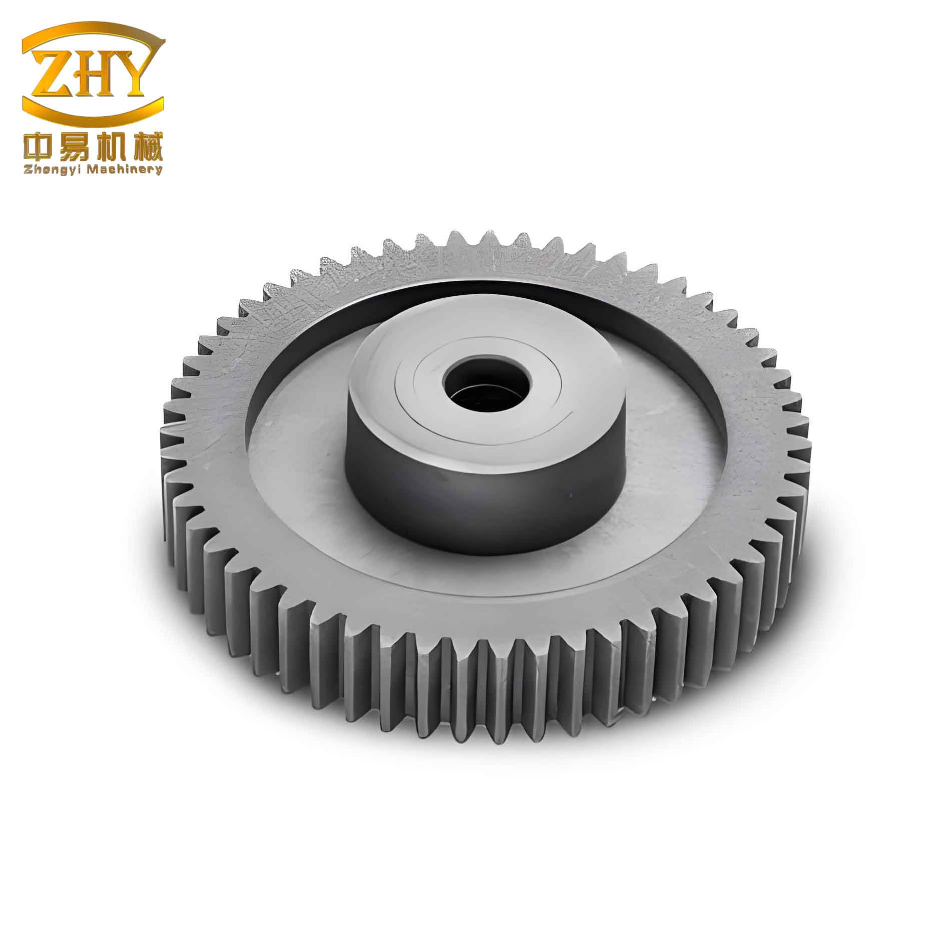
To begin with, understanding the base tooth profile is crucial for spur and pinion gears. Different countries adhere to varying standards for involute gear齿形, which直接影响 the模数 or径节 and压力角. For instance,模数制 systems (e.g., in China, Germany, Japan) use the module (m) and typically a压力角 of 20°, while径节制 systems (e.g., in the USA, UK) use the diametral pitch (DP) with压力角 values such as 14.5°, 16°, 20°, 22.5°, or 25°. When dealing with spur and pinion gears from international sources, identifying the country of origin can provide initial clues about the likely基准齿形. Below is a comparative table summarizing the common involute base tooth profiles for spur and pinion gears across major industrialized nations, which I have compiled based on my work with various gear systems.
| Country | Tooth Profile Type | Standard | Module (m) or Diametral Pitch (DP) | Pressure Angle (α) in degrees | Addendum Coefficient (ha*) | Dedendum Coefficient (c*) |
|---|---|---|---|---|---|---|
| International | Standard | ISO R53—1998 | m | 20 | 1 | 0.25 |
| China | Standard | GB/T 1356—2001 | m | 20 | 1 | 0.25 |
| USA | Standard | ASA B61—1932 | DP | 14.5 | 1 | 0.157 |
| USA | Standard | ASA B61—1958 | DP | 20 | 1 | 0.157 |
| Germany | Standard | DIN 867—1986 | m | 20 | 1 | 0.1–0.5 |
| Japan | Standard | JIS B1701—1963 | m | 20 | 1 | 0.25 |
| UK | Standard | BS 436—1940 | DP | 20 | 1 | 0.35 |
For spur and pinion gears, determining the base tooth profile often relies on measuring the base pitch (Pb), which is the distance between parallel lines tangent to corresponding profiles of adjacent teeth on the base circle. The most accurate and convenient method for this is the measurement of the common normal length, commonly referred to as the公法线 length. In my practice, I have found this approach particularly effective for spur and pinion gears, as it minimizes errors from wear or manufacturing imperfections. The procedure involves calculating the number of teeth spanned (k) for measurement, then measuring the公法线 lengths to derive the base pitch.
The number of teeth to span, k, for a spur gear can be estimated using the formula for standard gears, but for spur and pinion gears with potential modification, a more general expression is used. For spur gears, the approximate span number is given by: $$ k = \frac{z}{180^\circ} \alpha + 0.5 $$ where z is the number of teeth and α is the pressure angle in degrees. However, this may need adjustment for non-standard spur and pinion gears. Once k is determined, measure the common normal lengths Wk* and Wk-1* (or Wk+1*) using a gear tooth caliper or micrometer. It is essential to ensure that the caliper jaws are tangent to the involute profiles near the pitch circle for accuracy. From these measurements, the base pitch is computed as: $$ P_b = W_k^* – W_{k-1}^* $$ This base pitch value is then compared against standard tables to identify the module or diametral pitch and pressure angle for the spur and pinion gear. For example, a base pitch of 24.1 mm might correspond to a DP=3 and α=25° for a径节制 spur gear, while 58.96 mm could indicate m=20 and α=20° for a模数制 spur and pinion gear.
After establishing the base tooth profile, the next step is to determine the modification coefficient (x), which accounts for profile shifts in spur and pinion gears. This is critical for ensuring proper meshing and performance. The modification coefficient can be derived from the measured common normal length using the formula: $$ x = \frac{W’ – W^*}{2m \sin \alpha} $$ where W’ is the measured common normal length, W* is the theoretical common normal length for a non-modified spur gear, m is the module, and α is the pressure angle. For径节制 spur and pinion gears, the formula adapts to use DP instead of m. In my experience, this method is reliable for spur and pinion gears with minimal wear, but it can be influenced by tooth surface damage, so verification through other means is advisable. Alternatively, the tooth thickness measurement can be used, but the common normal method is often preferred for its simplicity and independence from tip diameter errors.
To validate the测绘 parameters for spur and pinion gears, it is essential to cross-check with other dimensional measurements, such as the tip diameter (da), root diameter (df), and center distance (a). These values can be calculated using the derived parameters and compared against实测 data. For instance, the tip diameter for a spur gear is given by: $$ d_a = m(z + 2 + 2x) $$ for模数制 spur and pinion gears, or $$ d_a = \frac{z + 2 + 2x}{DP} $$ for径节制 spur and pinion gears. Similarly, the root diameter is: $$ d_f = m(z – 2.5 + 2x) $$ or $$ d_f = \frac{z – 2.5 + 2x}{DP} $$ depending on the system. The center distance for a pair of spur and pinion gears is: $$ a = \frac{m(z_1 + z_2)}{2} + m(x_1 + x_2) $$ for模数制, and $$ a = \frac{z_1 + z_2}{2DP} + \frac{x_1 + x_2}{DP} $$ for径节制. Discrepancies between calculated and measured values may indicate errors in测绘 or the need for parameter adjustment.
Let me illustrate these concepts with a practical example involving spur and pinion gears from an American-made减速箱. In this case, the goal was to replicate a worn spur gear and its mating pinion for a mining application. The measured data were as follows: for the pinion (Z1 = 26), W4 = 90.76 mm, W5 = 114.86 mm, da1 = 238.4 mm, df1 = 197 mm; for the spur gear (Z2 = 37), W5 = 116.41 mm, W6 = 140.52 mm, da2 = 329.8 mm, df2 = 288.5 mm; and the center distance a’ = 267 mm. First, I computed the base pitch for both spur and pinion gears: for the pinion, Pb1 = 114.86 – 90.76 = 24.1 mm; for the spur gear, Pb2 = 140.52 – 116.41 = 24.11 mm. The consistency confirmed accurate measurements. Referring to base pitch tables, this matched a径节制 system with DP=3 and α=25°, typical for American spur and pinion gears.
Next, I determined the modification coefficients for the spur and pinion gears. Using the common normal lengths, for the pinion: $$ x_1 = \frac{90.76 – W_4^*}{2 \cdot (1/3) \sin 25^\circ} $$ where the module equivalent is m = 25.4/DP ≈ 8.467 mm for DP=3, but in径节制, calculations often use DP directly. Alternatively, using the formula with DP: $$ x = \frac{W’ – W^*}{2 \cdot (1/DP) \sin \alpha} $$ I obtained x1 ≈ 0.0583 and x2 ≈ -0.0780 for the spur gear. However, considering the center distance, the total modification coefficient needed adjustment. The theoretical center distance based on these x values was calculated and compared with a’ = 267 mm. Using the formula for径节制 spur and pinion gears: $$ a = \frac{z_1 + z_2}{2DP} + \frac{x_1 + x_2}{DP} $$ I derived a total modification coefficient shift of ΔΣx = 0.0522, which was distributed to yield final values of x1 = 0.0859 and x2 = -0.0505. Finally, I verified these by computing tip and root diameters: for the pinion, da1 = (26 + 2 + 2*0.0859)/3 ≈ 238.5 mm, and df1 = (26 – 2.5 + 2*0.0859)/3 ≈ 197.8 mm, closely matching the实测 data. This process underscored the importance of iterative validation in spur and pinion gear测绘.
Another example involves a German spur gear, where I dealt with a single spur gear without its mating pinion initially. The data were: Z = 21, W3 = 160.6 mm, W4 = 219.56 mm, da = 481.5 mm, df = 383.2 mm. The base pitch was Pb = 219.56 – 160.6 = 58.96 mm, indicating a模数制 spur gear with m=20 and α=20°. The modification coefficient from common normal measurements was x ≈ 0.5168, but after considering typical German standards (ha* = 1, c* = 0.167), the calculated diameters deviated significantly from实测 values. Upon further research, I discovered that this spur gear was part of a pair with a pinion of Z=13 and a center distance of 359.6 mm. To achieve proper meshing and重合度 (contact ratio), the spur gear likely had a non-standard addendum coefficient. By assuming ha* = 1.2 and c* = 0.267 for磨前滚刀加工, the recalculated da = 481.86 mm and df = 382.39 mm aligned well with measurements. This case highlights how spur and pinion gear interactions can influence individual gear parameters, necessitating a holistic approach.
In addition to these manual methods, modern computational tools have revolutionized spur and pinion gear metrology. Software packages can simulate gear meshing, calculate stresses, and optimize parameters based on实测 data. However, the fundamental principles remain rooted in the formulas and tables discussed. For instance, the contact ratio for a pair of spur and pinion gears is given by: $$ \epsilon_{\alpha} = \frac{1}{2\pi} \left[ \sqrt{(d_{a1}^2 – d_{b1}^2)} + \sqrt{(d_{a2}^2 – d_{b2}^2)} – a \sin \alpha \right] / m \cos \alpha $$ where db is the base diameter. A minimum contact ratio of 1.2 is often required for smooth operation of spur and pinion gears, which can guide parameter adjustments during测绘.
Moreover, the application of spur and pinion gears extends across industries, from automotive transmissions to industrial machinery. In my work, I have encountered spur and pinion gears in conveyor systems, where precise测绘 is essential for preventing downtime. The wear and tear on spur and pinion gears can be monitored through periodic common normal measurements, allowing for predictive maintenance. For example, an increase in common normal length over time might indicate tooth wear or plastic deformation in a spur gear, necessitating replacement or adjustment of the mating pinion.
To further elaborate on the formulas used in spur and pinion gear calculations, here is a summary of key equations in LaTeX format:
1. Base pitch: $$ P_b = \pi m \cos \alpha $$ for模数制 spur gears, and $$ P_b = \frac{\pi}{DP} \cos \alpha $$ for径节制 spur and pinion gears.
2. Common normal length for a non-modified spur gear: $$ W^* = m \cos \alpha [ (k – 0.5) \pi + z \cdot \text{inv} \alpha ] $$ where inv α is the involute function: $$ \text{inv} \alpha = \tan \alpha – \alpha $$ (with α in radians).
3. Tip diameter: $$ d_a = m(z + 2h_a^* + 2x) $$ or $$ d_a = \frac{z + 2h_a^* + 2x}{DP} $$ for spur and pinion gears.
4. Root diameter: $$ d_f = m(z – 2h_a^* – 2c^* + 2x) $$ or $$ d_f = \frac{z – 2h_a^* – 2c^* + 2x}{DP} $$.
5. Center distance: $$ a = \frac{m(z_1 + z_2)}{2} + m(x_1 + x_2) $$ or $$ a = \frac{z_1 + z_2}{2DP} + \frac{x_1 + x_2}{DP} $$ for spur and pinion gear pairs.
These equations are instrumental in spur and pinion gear测绘, and I often use them in spreadsheets for quick calculations. Additionally, the following table compares the geometric properties of spur and pinion gears under different modification scenarios, which can aid in parameter selection during reverse-engineering.
| Parameter | Standard Spur Gear (x=0) | Positive Modification Spur Gear (x>0) | Negative Modification Pinion (x<0) | Units |
|---|---|---|---|---|
| Tip Diameter | m(z+2) | m(z+2+2x) | m(z+2+2x) | mm |
| Root Diameter | m(z-2.5) | m(z-2.5+2x) | m(z-2.5+2x) | mm |
| Common Normal Length | W* | W* + 2m x sin α | W* + 2m x sin α | mm |
| Contact Ratio | εα (base value) | May increase or decrease | May increase or decrease | Dimensionless |
In conclusion, spur and pinion gear metrology is a meticulous yet rewarding discipline that blends theoretical knowledge with practical skills. Through methods like common normal measurement and base pitch analysis, engineers can accurately determine the design parameters of spur and pinion gears, even in the absence of original drawings. The repeated emphasis on ‘spur and pinion’ throughout this article reflects their ubiquity in mechanical systems and the need for precise handling. Whether dealing with模数制 or径节制 systems, the core principles remain consistent: measure carefully, calculate rigorously, and validate thoroughly. As technology advances, tools for spur and pinion gear analysis will become more sophisticated, but the fundamentals outlined here will continue to serve as the cornerstone for reliable gear engineering and maintenance.
Finally, I encourage practitioners working with spur and pinion gears to document their测绘 processes and share insights, as each case can offer unique lessons. The interplay between spur gears and pinions in a传动 system is delicate, and even minor errors in parameter estimation can lead to premature failure or inefficiency. By adhering to the steps described—from identifying the base tooth profile to refining modification coefficients—one can ensure that spur and pinion gears perform optimally in their intended applications, be it in heavy machinery or precision instruments.