
The coordinate transformation of the right tooth surface of the workpiece generated from the imaginary profile rack is shown in Figure 1. The reference coordinate system St of the rack cutter is built on the left tooth surface, and the left tooth surface can be obtained through the coordinate transformation. In the figure α N is the normal pressure angle, β Is the spiral angle of the indexing circle, θ 1 is the angle of helical gear, r p1 is the radius of the indexing circle; am=0.25πmn/cos β, Represents 1/4 end face pitch; Mn represents the normal modulus of helical gear. Assume that the position vector and unit normal vector of the right flank of the rack cutter are rt=[ut, 0, lt, 1] ^ T, nt=[0, 1, 0] ^ T, where ut and lt are the coordinate parameters on the xt axis and zt axis of the right flank of the rack cutter. According to the helical gear meshing principle, the position vector r1 (ut, lt, θ 1) , unit normal n1 (ut, lt, θ 1) And the meshing equation is expressed as:
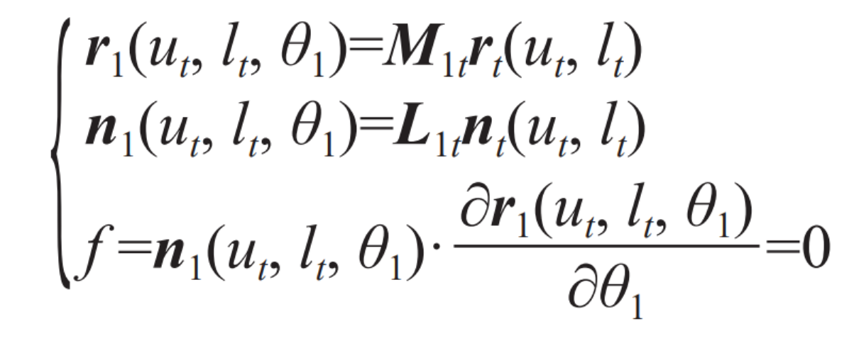
Where, M1t=M1fMfaMabMbcMcdMdt, M1t is the transformation matrix from the rack tool reference coordinate system St to the workpiece dynamic coordinate system S1, and L1t is the transformation sub-matrix of M1t with the last row and last column removed.