
In the realm of high-power, high-torque transmission systems for marine propulsion and aerospace applications, the demand for compact, reliable, and efficient gearboxes is paramount. Among the various configurations, coaxial multi-branch transmission systems utilizing herringbone gears have garnered significant attention. These systems are characterized by their coaxial input and output shafts, a feature that contributes to a compact structural layout. The power is divided and transmitted through multiple parallel paths before being recombined, leading to a substantial increase in torque capacity and overall system reliability due to inherent redundancy. The unique double-helical design of herringbone gears effectively cancels out axial thrust loads, simplifying bearing arrangements and enhancing operational stability under heavy loads.
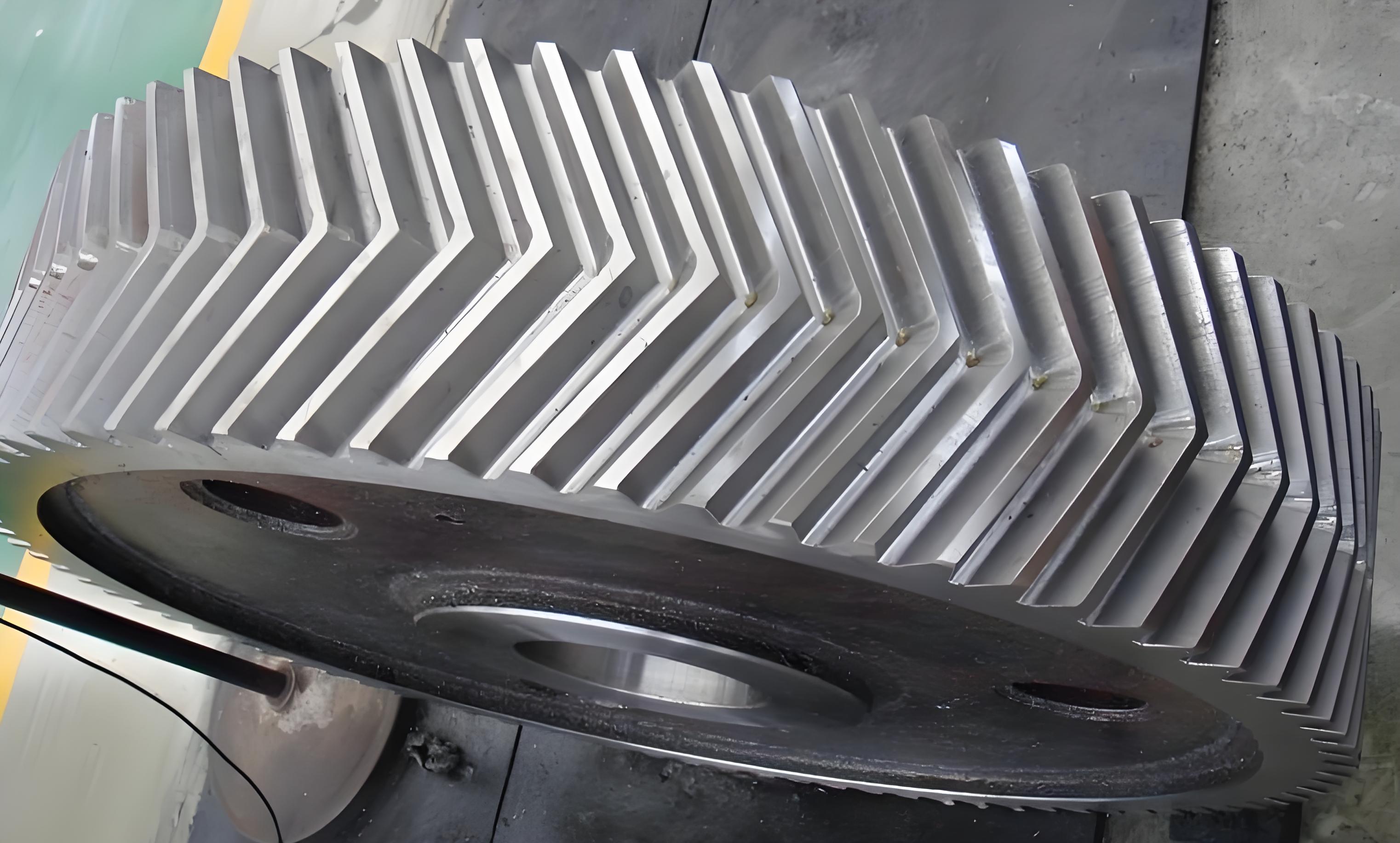
However, the superior performance of these multi-path systems is critically dependent on achieving equal load distribution among the parallel branches. Uneven load sharing, where one or more paths carry a disproportionately high load, can lead to premature wear, pitting, and even catastrophic failure of the herringbone gears and associated components. This load imbalance primarily stems from system imperfections, namely manufacturing errors (e.g., gear eccentricity, pitch deviation, tooth thickness variation) and assembly errors (e.g., misalignments of shafts and bearings). For large, low-speed systems like marine gearboxes, a static load-sharing analysis during the design phase is of utmost importance. It provides the foundational load distribution factors necessary for strength calculations and paves the way for subsequent dynamic analyses.
This article presents a comprehensive static load-sharing analysis methodology for a coaxial six-branch power-split transmission system employing herringbone gears. The analysis begins by establishing the static force equilibrium equations based on the force state of each gear pair. Subsequently, a detailed model incorporating various error sources is developed. The deformation compatibility conditions, which are fundamental to closed-loop power transmission systems, are then formulated. Finally, a numerical case study is conducted to quantify the impact of different error types and magnitudes on the system’s static load-sharing performance.
System Configuration and Static Force Equilibrium
The system under investigation is a two-stage coaxial six-branch transmission. The power flow can be described as follows: Input power is delivered to the first-stage pinion (Gear 1). This power is then split into three parallel paths via three first-stage idler gears (Gears 21, 22, 23). Each idler gear drives a first-stage bull gear (Gears 31, 32, 33). These bull gears are connected through compliant torsion shafts to second-stage pinions (Gears 41, 42, 43). Each of these second-stage pinions further splits the power into two paths, engaging with two second-stage idler gears (Gears 51-56). Ultimately, all six secondary paths converge onto the final output bull gear (Gear 6). This configuration achieves a high reduction ratio and massive torque multiplication through six parallel load paths.
To analyze the static load distribution, a lumped-parameter model is constructed. Each herringbone gear is idealized as a rigid disk. The elastic deformations at the gear meshes and bearing supports are represented by equivalent linear springs. The static meshing force between gear \(i\) and gear \(j\) is denoted as \(F_{ij}\), acting along the line of action. The base radius of gear \(i\) is \(r_{bi}\).
The static equilibrium equations are derived by summing moments about the center of each gear. For the input pinion (Gear 1), equilibrium requires that the input torque is balanced by the sum of the meshing forces from the three first-stage idlers:
$$
T_1 + F_{121} \cdot r_{b1} + F_{122} \cdot r_{b1} + F_{123} \cdot r_{b1} = 0
$$
For a typical first-stage idler gear (e.g., Gear 21), the force from the input pinion is balanced by the force from its corresponding bull gear:
$$
-F_{121} \cdot r_{b21} + F_{2131} \cdot r_{b21} = 0 \quad \Rightarrow \quad F_{121} = F_{2131}
$$
Similar equations hold for Gears 22 and 23. For the compound gears (31-41, 32-42, 33-43), which are rigidly connected, the equilibrium involves forces from two stages. For the compound gear in path 1 (Gears 31-41):
$$
-F_{2131} \cdot r_{b31} + F_{4151} \cdot r_{b41} + F_{4152} \cdot r_{b41} = 0
$$
For the second-stage idler gears (e.g., Gear 51), equilibrium is between the force from the second-stage pinion and the force to the output gear:
$$
-F_{4151} \cdot r_{b51} + F_{516} \cdot r_{b51} = 0 \quad \Rightarrow \quad F_{4151} = F_{516}
$$
By systematically applying equilibrium to all gears and recognizing symmetry in gear radii within each stage (\(r_{b21}=r_{b22}=r_{b23}=r_{b2}\), etc.), a global relationship between input torque and total output mesh forces can be derived. The final consolidated equation highlights the torque balance:
$$
\frac{T_1}{r_{b1}} + \frac{(F_{516} + F_{526} + F_{536} + F_{546} + F_{556} + F_{566}) \cdot r_{b4}}{r_{b3}} = 0
$$
This equation, while essential, contains multiple unknown mesh forces. To solve for each individual \(F_{ij}\), the geometric constraints imposed by errors and elastic deformations must be introduced through compatibility equations.
Modeling of Meshing Errors
The primary cause of load imbalance in a perfectly symmetric system is the presence of discrepancies in the kinematic path lengths of each branch. These discrepancies arise from errors. To analyze their effect, all errors are projected onto the line of action of each gear mesh, resulting in an equivalent mesh error. This error represents the apparent displacement along the contact line that would occur if the gears were rigid, effectively altering the “tightness” of each mesh.
Equivalent Angular Error due to Manufacturing and Assembly
Errors are classified into manufacturing errors (varying with gear rotation) and assembly errors (fixed in space). Let \(E_{ri}\) and \(\beta_i\) be the magnitude and angular orientation (from the x-axis) of the radial manufacturing error (eccentricity) for gear \(i\). Let \(A_{ri}\) and \(\gamma_i\) be the magnitude and orientation of its radial assembly error. The pressure angle for the mesh between gear \(i\) and \(j\) is \(\alpha_{ij}\), and \(\psi_{ij}\) is the position angle of gear \(j\) relative to gear \(i\).
The equivalent angular error contribution on gear \(i\) at its mesh with gear \(j\), caused by its own eccentricity \(E_{ri}\), is given by:
$$
\varphi_{Erij} = -\frac{E_{ri}}{r_i} \sin(\omega_i t + \beta_i + \alpha_{ij} – \psi_{ij})
$$
The contribution from gear \(j\)’s eccentricity at the same mesh is:
$$
\varphi_{Erji} = +\frac{E_{rj}}{r_j} \sin(-\omega_j t + \beta_j + \alpha_{ij} – \psi_{ij})
$$
Similarly, contributions from pitch error \(E_{bpi}\) and tooth thickness error \(E_{tpi}\) are constant angular errors:
$$
\varphi_{Ebpi} = -\frac{E_{bpi}}{r_i}, \quad \varphi_{Etpi} = -\frac{E_{tpi}}{r_i}
$$
Assembly errors contribute fixed angular errors. For gear \(i\)’s assembly error:
$$
\varphi_{Arij} = -\frac{A_{ri}}{r_i} \sin(\gamma_i + \alpha_{ij} – \psi_{ij})
$$
And for gear \(j\):
$$
\varphi_{Arji} = +\frac{A_{rj}}{r_j} \sin(\gamma_j + \alpha_{ij} – \psi_{ij})
$$
Equivalent Error due to Floating Components
Floating the input and/or output gears is a common design practice to promote self-alignment and improve load sharing. The translational displacements \((x_1, y_1)\) of the input gear and \((x_6, y_6)\) of the output gear create an effective change in backlash \(\Delta_{ij}\) at their respective meshes. If \(\nu_{ij}\) is the direction angle of the line of action for mesh \(i\)-\(j\), this change is:
$$
\Delta_{121} = – (x_1 \cos\nu_{121} + y_1 \sin\nu_{121}) / r_{b1}
$$
A similar expression holds for \(\Delta_{516}\), etc., with \(x_6\) and \(y_6\).
Total Composite Mesh Error
The total equivalent angular error \(e_{ij}\) for a mesh between gear \(i\) and \(j\) is the linear superposition of all contributing error projections and the floating displacement effect. For example, for the mesh between the input gear and the first idler in path 1:
$$
\begin{aligned}
e_{121} = & \varphi_{Er121} + \varphi_{Eb121} + \varphi_{Er211} + \varphi_{Eb211} + \varphi_{Ebp1} + \varphi_{Ebp21} + \varphi_{Etp1} + \varphi_{Etp21} \\
& + \varphi_{Ar121} + \varphi_{Ar211} + \Delta_{121}
\end{aligned}
$$
Similar composite error expressions \(e_{2131}, e_{4151}, e_{516},\) etc., are defined for all 18 meshes in the six-branch system. These error terms \(e_{ij}\) are crucial inputs to the deformation compatibility conditions.
Deformation Compatibility and Load-Sharing Equations
In a statically indeterminate multi-path transmission system, the force in each path is determined by the requirement that the total deformation around any closed power loop must be consistent. The deformation at each mesh consists of two parts: 1) the elastic deflection due to the meshing force \(F_{ij}\) acting through the mesh stiffness \(k_{ij}\), and 2) the kinematic error \(e_{ij}\).
Consider any one of the six complete power paths from the input gear to the output gear. The net angular displacement at the output gear (Gear 6), contributed by all elements in that path, must be identical for all six paths. This is the deformation compatibility condition. For Path 1 (through Gears 1-21-31-41-51-6), the equivalent angular displacement at Gear 6, \(\Delta \phi_1^6\), is calculated by summing contributions from each mesh and the torsion shaft, referred to the output using gear ratios (\(i_{kl} = \omega_k / \omega_l\)).
$$
\begin{aligned}
\Delta \phi_1^6 = & \frac{e_{121}}{r_{b21} i_{2131} i_{4151} i_{516}} + \frac{F_{121}}{k_{121} r_{b21} i_{2131} i_{4151} i_{516}} \\
& + \frac{e_{2131}}{r_{b31} i_{4151} i_{516}} + \frac{F_{2131}}{k_{2131} r_{b31} i_{4151} i_{516}} + \frac{F_{2131} \cdot r_{b31}}{K_1 i_{4151} i_{516}} \\
& + \frac{e_{4151}}{r_{b51} i_{516}} + \frac{F_{4151}}{k_{4151} r_{b51} i_{516}} \\
& + \frac{e_{516}}{r_{b6}} + \frac{F_{516}}{k_{516} r_{b6}}
\end{aligned}
$$
Where \(K_1\) is the torsional stiffness of the shaft connecting Gears 31 and 41. Similar equations \(\Delta \phi_2^6, \Delta \phi_3^6, \ldots, \Delta \phi_6^6\) are written for the other five paths. The compatibility condition is:
$$
\Delta \phi_1^6 = \Delta \phi_2^6 = \Delta \phi_3^6 = \Delta \phi_4^6 = \Delta \phi_5^6 = \Delta \phi_6^6
$$
These five independent compatibility equations, together with the single global torque equilibrium equation derived earlier, form a system of six equations. However, they involve many more unknown mesh forces (\(F_{121}, F_{122}, …\)). The remaining equations come from the local equilibrium equations at each gear (e.g., \(F_{121}=F_{2131}\), \(F_{4151}=F_{516}\), etc.). Substituting these local equilibrium relations into the compatibility equations yields a solvable linear system where the primary unknowns are the six mesh forces at the output stage (\(F_{516}, F_{526}, …, F_{566}\)) or similar. Solving this system provides the static load distribution across all herringbone gear meshes.
Load-Sharing Coefficients and Numerical Case Study
Definition of Coefficients
To quantify load-sharing performance, two coefficients are defined. The mesh static load-sharing coefficient \(k_{sij}\) for a specific gear pair is the ratio of its calculated static force to its nominal force share:
$$
k_{sij} = \frac{F_{ij}}{T_i / r_{bi}}
$$
where \(T_i\) is the nominal torque on gear \(i\). A value of 1 indicates perfect load sharing for that mesh.
Since meshes in parallel are of greater concern, a branch static load-sharing coefficient \(K_{sk}\) is defined for each of the six power branches. It identifies the worst-case deviation from ideal sharing within that branch’s meshes:
$$
K_{sk} =
\begin{cases}
\min(k_{sij}) & \text{if } |\min(k_{sij}) – 1| > |\max(k_{sij}) – 1| \\
\max(k_{sij}) & \text{if } |\min(k_{sij}) – 1| < |\max(k_{sij}) – 1|
\end{cases}
\quad \text{for meshes } ij \text{ in branch } k
$$
A branch coefficient \(K_{sk}\) closer to 1 signifies better overall load distribution for that path.
System Parameters
The analysis is applied to a representative marine gear system. Key parameters are summarized below:
| Gear Stage | Gear Designation | Number of Teeth, Z | Normal Module, m_n (mm) | Helix Angle, β (°) |
|---|---|---|---|---|
| Stage I (Split) | Input Pinion (1) | 52 | 6 | 28 |
| Idlers (21,22,23) | 70 | 6 | 28 | |
| Bull Gears (31,32,33) | 221 | 6 | 28 | |
| Stage II (Combine) | Pinions (41,42,43) | 44 | 8 | 29 |
| Idlers (51-56) | 84 | 8 | 29 | |
| Output Gear (6) | 207 | 8 | 29 |
Input power \(P = 30,000 \text{ kW}\) at speed \(n = 4000 \text{ rpm}\). Torsional stiffness of inter-stage shafts \(K_1 = K_2 = K_3 = 3.863 \times 10^{10} \text{ N·m/rad}\). Average mesh stiffnesses for the herringbone gears are on the order of \(1.8-3.0 \times 10^{10} \text{ N/m}\).
Results and Discussion
1. Ideal (Error-Free) Condition: In the absence of any errors or with identical constant errors across all gears, the system exhibits perfect static load sharing. All mesh forces reach their nominal values, and all load-sharing coefficients are exactly 1. The calculated static meshing forces are:
$$ F_{\text{I}} = 1.773 \times 10^5 \text{ N} \quad \text{(for Stage I meshes)} $$
$$ F_{\text{II}} = 3.673 \times 10^5 \text{ N} \quad \text{(for Stage II meshes)} $$
This result confirms the inherent potential for perfect load distribution in a symmetric coaxial multi-branch system with herringbone gears, as errors in a closed loop can theoretically cancel out.
2. Effect of Manufacturing vs. Assembly Errors: When realistic, non-uniform errors are introduced, load imbalance occurs. The table below shows the branch load-sharing coefficients \(K_{s1}, K_{s4}, K_{s7}, K_{s13}\) (representative of first-stage split, first-stage combine, second-stage split, and second-stage combine meshes, respectively) under two scenarios: (a) only manufacturing errors present (50 μm amplitude), and (b) only assembly errors present (50 μm amplitude).
| Error Scenario | \(K_{s1}\) | \(K_{s4}\) | \(K_{s7}\) | \(K_{s13}\) |
|---|---|---|---|---|
| Manufacturing Errors Only (50μm) | 1.0178 | 1.9840 | 0.9186 | 1.0843 |
| Assembly Errors Only (50μm) | 1.0789 | 1.2188 | 0.9156 | 0.7599 |
The analysis reveals that manufacturing errors generally cause a larger deviation in the load-sharing coefficients compared to assembly errors of the same magnitude. For instance, \(K_{s4}\) deviates to 1.984 under manufacturing errors but only to 1.219 under assembly errors. This indicates that the geometric imperfections inherent in the herringbone gears themselves (eccentricity, pitch) have a more pronounced detrimental effect on static load distribution than fixed assembly misalignments. Therefore, stringent control of gear manufacturing precision is critical for optimal performance of these systems.
3. Effect of Errors in Different Stages: The sensitivity to errors varies between the first (power-split) stage and the second (power-combine) stage. The following results are obtained when errors exist only in one stage at a time (50 μm amplitude).
| Error Location | \(K_{s1}\) | \(K_{s4}\) | \(K_{s7}\) | \(K_{s13}\) |
|---|---|---|---|---|
| Errors in Split Stage Only | 0.9655 | 0.9475 | 1.0175 | 1.0375 |
| Errors in Combine Stage Only | 0.8898 | -0.8898 | 0.8996 | 1.1102 |
A key observation is the negative value of \(K_{s4}\) when errors are concentrated in the combine stage. A negative load-sharing coefficient indicates that the calculated static meshing force has reversed direction, which in a real system would correspond to a loss of contact or severe backlash condition in that particular mesh/branch. This highlights that the second (combine) stage, where six paths converge onto a single output herringbone gear, is significantly more sensitive to errors and prone to severe load maldistribution than the first (split) stage. This finding strongly justifies the common practice of incorporating a floating design for the output gear (Gear 6), allowing it to self-center and better equalize the loads from all six input meshes.
Conclusion
This article has presented a systematic methodology for analyzing the static load-sharing performance of complex coaxial multi-branch transmission systems employing herringbone gears. The model integrates static force equilibrium, comprehensive error modeling (manufacturing, assembly, and floating displacements), and deformation compatibility conditions essential for closed-loop power transmission.
The key findings from the numerical case study are:
- In an ideal symmetric system, perfect static load sharing is achievable, demonstrating the theoretical potential of coaxial multi-branch herringbone gear systems.
- Manufacturing errors in the herringbone gears have a more significant adverse impact on load distribution compared to assembly errors of comparable magnitude. This underscores the importance of high-precision gear manufacturing.
- The final power-combine stage is substantially more sensitive to errors than the initial power-split stage. Errors here can lead to extreme load imbalance and even loss of contact, validating the necessity of using a floating output mechanism to enhance system robustness and load-sharing capability.
The developed analytical framework provides a powerful tool for designers. It enables the determination of realistic load distribution factors for strength and durability calculations during the design phase of marine and aerospace gearboxes. Furthermore, it offers scientific guidance for specifying tolerance levels for gear manufacturing and system assembly to ensure reliable operation of high-power herringbone gear transmission systems.