
In my research on helical gears, I have investigated the dynamic behavior under the influence of stick-slip friction. Traditional sliding models often neglect the adhesion effect, failing to capture the real meshing dynamics. To address this, I developed a comprehensive dynamic model for helical gear pairs incorporating time-varying friction coefficients and stick-slip transitions. I established the conditions for switching between stick and slip states and integrated them into the differential equations of motion. By comparing the responses under pure slip and stick-slip regimes, I analyzed variations in friction coefficient, meshing force, and friction force. Key findings reveal that at the pitch point, relative sliding velocity vanishes, causing the friction coefficient to approach zero. Near the pitch point, the friction coefficient decreases, while away from it, the coefficient increases. The friction coefficient decreases with rising rotational speed and increases with higher load. Stick-slip phenomena become more pronounced under high-speed, heavy-load conditions. Increasing load prolongs the sticking duration per tooth engagement, raising the probability of adhesive wear. Higher rotational speeds amplify vibration frequencies and increase the occurrence of stick contacts. When accounting for stick-slip, the single-tooth meshing force exhibits intense oscillations near the stick region, and the dynamic response of the single-tooth friction force becomes more complex, indicating that stick-slip significantly amplifies fluctuations in both meshing and friction forces.
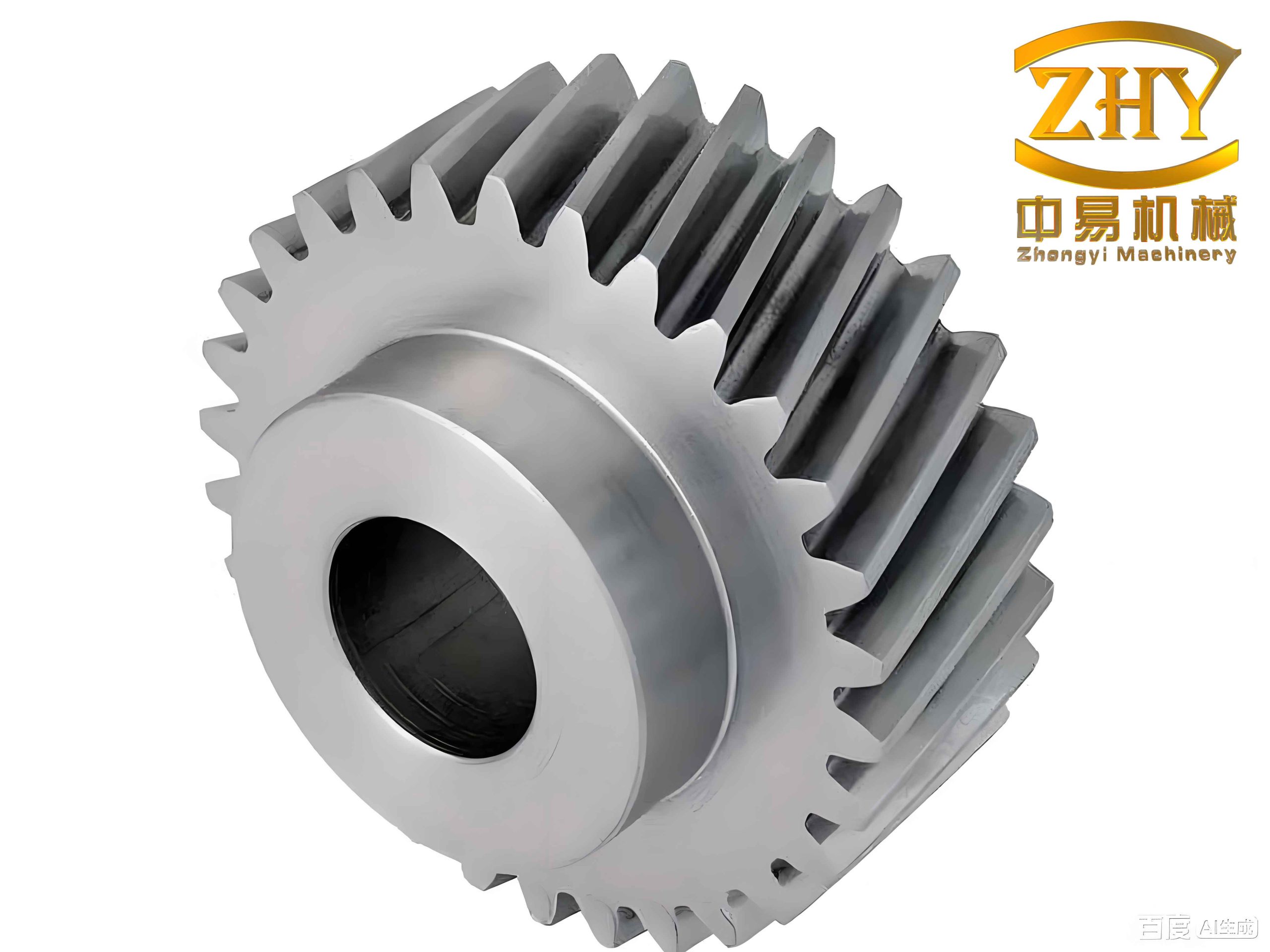
1. Introduction
Gear friction is a critical factor influencing the dynamic performance, noise, vibration, and service life of transmission systems. In helical gears, the meshing process involves complex contact kinematics with sliding and rolling motions. The friction force at the tooth interface acts as a non-harmonic internal excitation, causing vibrations and noise. Conversely, friction can also provide damping that reduces displacement fluctuations. In practice, low-speed and heavy-load conditions often lead to dry friction and severe wear. Understanding the stick-slip phenomenon — the periodic alternation between sticking and sliding — is essential because it induces self-excited oscillations and negatively affects gear dynamics. Although previous studies have explored gear friction with time-varying coefficients, few have considered the adhesion effect in helical gears. In this work, I aim to fill this gap by developing a dynamic model for helical gears that explicitly incorporates stick-slip transitions based on relative velocity and friction force thresholds. I examine how load, speed, and mesh position influence the friction coefficient and the occurrence of stick-slip events.
2. Dynamic Model of Helical Gear Pair with Stick-Slip
I consider an eight-degree-of-freedom (8-DOF) dynamic model for a helical gear pair. Each gear has three translational degrees of freedom (x, y, z) and one rotational degree of freedom about the z-axis. The model includes time-varying mesh stiffness and damping, support stiffness and damping, input torque, and load torque. The basic parameters of the helical gear pair are listed in Table 1.
| Parameter | Value |
|---|---|
| Number of teeth (Z1/Z2) | 29/69 |
| Helix angle βb (°) | 20 |
| Normal module mn (mm) | 7 |
| Actual center distance a (mm) | 363 |
| Pressure angle αn (°) | 26 |
| Face width b (mm) | 70 |
The mesh kinematics for helical gears is more complex than spur gears because the contact line is inclined. At any meshing position, the relative sliding velocity vs, rolling velocity vr, slide-to-roll ratio SR, and entrainment velocity ve are defined as:
$$ v_{s} = v_1 – v_2 $$
$$ v_{r} = v_1 + v_2 $$
$$ SR = \frac{2 v_s}{v_r} $$
$$ v_e = \frac{v_r}{2} $$
The dynamic mesh force Fn is given by:
$$ F_n = K_m \delta(t) + C_m \dot{\delta}(t) $$
where δ(t) is the relative displacement along the line of action, and Km and Cm are the time-varying mesh stiffness and damping. The friction force Ff is:
$$ F_f = \mu F_n $$
with μ being the time-varying friction coefficient.
The equations of motion for the 8-DOF system are derived using Newton’s second law. To eliminate rigid-body motion, I introduce a relative coordinate δ, reducing the system to a set of dimensionless equations. The complete set of equations is too lengthy to reproduce here, but they include terms for translational vibrations in x, y, z directions for both gears, rotational vibrations, and the relative meshing coordinate. The stick-slip condition is central to this study.
3. Time-Varying Friction Coefficient of Helical Gears
I adopt the improved elastohydrodynamic lubrication (EHL) friction coefficient model proposed by Xu et al., which accounts for surface roughness, oil viscosity, equivalent curvature radius, and contact pressure. The formula is:
$$ \mu = e^{f(SR, p_h, \nu_0, \sigma)} \cdot p_h^{b_2} \cdot |SR|^{b_3} \cdot v_e^{b_6} \cdot \nu_0^{b_7} \cdot R^{b_8} $$
where the function f is:
$$ f(SR, p_h, \nu_0, \sigma) = b_4 SR p_h \log_{10}(\nu_0) + b_5 e^{|SR| p_h \log_{10}(\nu_0)} + b_9 e^{\sigma} + b_1 $$
The coefficients b1 through b9 depend on the lubricant type and are listed in Table 2. The parameters used in my simulations are: gear material 20CrNi2Mo (E = 206 GPa, Poisson’s ratio 0.3), surface roughness σ = 1.13 μm, lubricant 75W-90 with dynamic viscosity ν0 = 13.5 mPa·s, and gear face width 70 mm.
| Coefficient | Value |
|---|---|
| b1 | -8.92 |
| b2 | 1.03 |
| b3 | 1.04 |
| b4 | -0.35 |
| b5 | 2.81 |
| b6 | -0.1 |
| b7 | 0.75 |
| b8 | -0.39 |
| b9 | 0.62 |
I used a slicing method to compute the mesh force distribution. The helical gear tooth is divided into m slices, each treated as a spur gear. The total meshing force is the sum of forces on all slices. By this model, I obtained the variation of friction coefficient over one mesh cycle under different loads and speeds. Figure 4 and Figure 5 (not labeled in text) show typical results. The friction coefficient decreases with increasing sliding speed, exhibiting a negative slope that is known to cause stick-slip instability. At the pitch point, the friction coefficient approaches zero because the relative sliding velocity vanishes. Near the pitch point, the friction coefficient decreases gradually, and away from the pitch point, it increases. In the double-triple tooth transition zone, the friction coefficient experiences a sudden change due to load redistribution. The friction coefficient is larger during the approach phase than the recess phase due to higher contact pressure and slide-to-roll ratio. Higher loads increase the contact pressure and thus the friction coefficient; higher speeds increase entrainment velocity and reduce the friction coefficient.
The influence of load and speed on the average friction coefficient is summarized in Table 3.
| Condition | Trend of μ |
|---|---|
| Increase in torque T (load) | Increases |
| Increase in rotational speed n | Decreases |
| Near pitch point | Approaches zero |
| Far from pitch point (approach side) | Higher than recess side |
4. Stick-Slip Transition Conditions
In the meshing process of helical gears, the relative sliding velocity between tooth surfaces changes direction at the pitch point. When the relative velocity becomes zero and the static friction force is sufficient to prevent sliding, the teeth stick together. I defined the stick-slip transition conditions as follows:
- Slip state: The relative sliding velocity vr ≠ 0, and the friction force is kinetic friction: Ff = μk Fn.
- Stick state: The relative sliding velocity vr = 0 and the static friction force required to maintain zero relative velocity does not exceed the maximum static friction: |fstick| < μs Fn.
Mathematically, the stick condition is:
$$ v_r = [v_{M2}\sin\alpha_2 – \dot{x}_2] – [v_{M1}\sin\alpha_1 – \dot{x}_1] = 0 $$
$$ f_{12} = f_{21} < \mu F_n $$
Here, vM1 and vM2 are the tangential velocities of the two gears at the mesh point, α1 and α2 are the pressure angles, and x1, x2 are the translational displacements. The stick friction force fstick is determined by the dynamic equilibrium of the system when the relative acceleration is also zero. I incorporated these conditions into the dynamic differential equations, replacing the slip friction force with the stick friction force during stick intervals.
5. Dynamic Characteristics Analysis under Stick-Slip
I simulated the dynamic response of the helical gear pair under both pure slip and stick-slip models. The key outputs include relative velocity, meshing force, and friction force for a single tooth. The simulation parameters include speeds from 500 to 1500 rpm and torques from 2000 to 4000 N·m.
5.1 Relative Velocity and Stick-Slip Occurrence
In the pure slip model, the relative velocity crosses zero only once at the pitch point, but due to vibration, multiple zero crossings may occur. In the stick-slip model, the relative velocity is exactly zero during sticking intervals. Figure 8 (not shown here) indicates that in each mesh cycle, there can be multiple stick events near the pitch point. As speed increases, the vibration frequency increases, leading to more frequent stick events. As load increases, the duration of each stick event becomes longer, increasing the probability of adhesive wear. Table 4 summarizes the number of stick events per mesh cycle for different conditions.
| Operating condition | Average stick events per cycle |
|---|---|
| n=500 rpm, T=2000 N·m | 1-2 |
| n=1000 rpm, T=2000 N·m | 2-3 |
| n=1500 rpm, T=2000 N·m | 3-4 |
| n=1000 rpm, T=3000 N·m | 2 (longer duration) |
| n=1000 rpm, T=4000 N·m | 2 (very long duration) |
5.2 Meshing Force Response
The dynamic meshing force in the pure slip model shows periodic fluctuations corresponding to the double-triple tooth alternating contact. When stick-slip is considered, the single-tooth meshing force experiences severe oscillations in the stick region. The amplitude of these oscillations can reach up to 150 kN, much higher than the nominal force. This indicates that stick-slip significantly amplifies the dynamic load. Table 5 compares the peak-to-peak values of the meshing force under different models.
| Model | Peak-to-peak force (kN) |
|---|---|
| Pure slip (n=1000 rpm, T=2000 N·m) | ~20 |
| Stick-slip (n=1000 rpm, T=2000 N·m) | ~70 |
5.3 Friction Force Response
The single-tooth friction force in the pure slip model reverses direction at the pitch point and maintains a relatively smooth profile. In the stick-slip model, the friction force exhibits sharp transitions between stick and slip. During stick, the friction force equals the force required to maintain zero relative velocity, which can be significantly higher than the kinetic friction. This leads to complex and irregular oscillations. The fluctuation amplitude of friction force under stick-slip is about 2-3 times larger than under pure slip.
I also examined the effect of rotational speed on the friction force dynamics. Higher speeds lead to more frequent stick events and higher-frequency force oscillations, which could contribute to gear noise and surface damage.
6. Conclusion
Based on my analysis of helical gear dynamics incorporating stick-slip friction, I draw the following conclusions:
- The time-varying friction coefficient for helical gears approaches zero at the pitch point and decreases near it, while increasing away from it. The coefficient decreases with rising speed and increases with higher load.
- Stick-slip phenomena occur in the vicinity of the pitch point when the relative sliding velocity becomes zero and the static friction is sufficient. High speed and heavy load promote stick-slip. Increasing load lengthens the sticking duration, increasing the risk of adhesive wear. Higher rotational speeds increase the frequency of stick events.
- Stick-slip significantly amplifies the fluctuations of both meshing force and friction force. The single-tooth meshing force experiences severe oscillations during stick intervals, with amplitudes several times larger than the nominal force. The friction force also becomes more complex and large in amplitude.
- These findings highlight the importance of considering stick-slip in the design and analysis of helical gears to avoid excessive vibration, noise, and surface damage. Appropriate selection of operating conditions and the use of damping can mitigate the adverse effects of stick-slip.
In future work, I plan to extend this model to include thermal effects and surface wear, and to validate the results with experimental measurements on helical gear test rigs.