1. Introduction
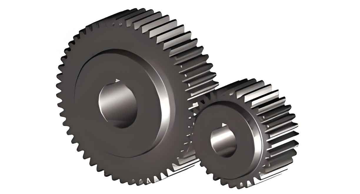
Spur gears are fundamental components in mechanical transmission systems, widely used in industries such as manufacturing, aerospace, and rail transport. Their precision and stability directly impact the performance of industrial equipment. However, challenges such as manufacturing errors, installation misalignments, and meshing interference during operation limit their applications. Gear modification techniques, including tooth profile modification and tooth alignment modification, have emerged as effective solutions to reduce meshing impacts, improve load distribution, and enhance transmission stability. This study systematically investigates the influence of modification parameters on the meshing stiffness and dynamic characteristics of spur gears, providing theoretical insights for optimizing gear design.

2. Literature Review
2.1 Gear Modification Research
Gear modification aims to minimize vibration and noise by altering tooth profiles or alignments. Key findings include:
- Tooth profile modification reduces meshing impacts by adjusting the tooth flank geometry.
- Tooth alignment modification addresses edge-loading issues by modifying the tooth width distribution.
| Author | Contribution | Key Finding |
|---|---|---|
| Wang et al. (2017) | Tooth alignment modification for spur gears | Reduced meshing stiffness peaks and shifted resonance frequencies. |
| Liu et al. (2018) | Profile modification for crossed beveloid gears | Improved contact paths and reduced transmission errors. |
| Zhang et al. (2019) | Nonlinear dynamics with profile errors | Demonstrated reduced dynamic load coefficients via optimized modifications. |
2.2 Stiffness Calculation Methods
Accurate meshing stiffness calculation is critical for dynamic analysis. Two primary methods are:
- Analytical Methods: Based on energy principles and beam theory.
- Finite Element Analysis (FEA): Provides high precision but requires significant computational resources.
2.3 Nonlinear Dynamics of Gears
Dynamic models incorporating time-varying stiffness, backlash, and damping reveal complex behaviors such as chaos and bifurcation. Recent studies highlight the role of modification parameters in stabilizing gear systems.
3. Gear Modification Methods
3.1 Tooth Profile Modification
3.1.1 Principle
Tooth profile modification involves removing material from the tip or root to avoid geometric interference during meshing. The maximum modification amount (CaCa), modification length (LaLa), and modification curve are critical parameters (Figure 1).
3.1.2 Key Formulas
- Ideal Modification Amount:Ca=δ+δ0+δmCa=δ+δ0+δmwhere δδ: elastic deformation, δ0δ0: thermal deformation, δmδm: manufacturing error.
- ISO Recommended Formula:Ca=kAFtbϵaCCa=bϵaCkAFt
3.2 Tooth Alignment Modification
3.2.1 Principle
Tooth alignment modification compensates for shaft deflection and load-induced deformations. Common methods include linear end relief and crowning (Figure 2).
3.2.2 Key Parameters
- Modification Ratio (ratBratB):ratB=LbBratB=BLbwhere LbLb: unmodified width, BB: total tooth width.
4. Stiffness Calculation of Modified Spur Gears
4.1 Analytical Method
The Improved Energy Method divides the gear into thin slices and calculates stiffness components (Figure 3):
- Bending stiffness (kbkb)
- Axial stiffness (kaka)
- Shear stiffness (ksks)
- Contact stiffness (khkh)
4.1.1 Stiffness Components
1ki=1kh1+kh2+1ks1+ks2+1kb1+kb2+1ka1+ka2ki1=kh1+kh21+ks1+ks21+kb1+kb21+ka1+ka21
4.2 Finite Element Validation
A spur gear pair (Table 1) was modeled in ANSYS Workbench to validate analytical results.
| Parameter | Value |
|---|---|
| Teeth (Z1/Z2) | 23/43 |
| Module (mm) | 4 |
| Pressure Angle (°) | 20 |
| Face Width (mm) | 50 |
Results showed a maximum error of 4.38% between analytical and FEA methods (Figure 5).
4.3 Effect of Modification Parameters
4.3.1 Tooth Profile Modification
- Modification Amount (CaCa): Higher CaCa reduces stiffness fluctuations but decreases double-tooth engagement (Figure 6).
- Modification Length (LaLa): Optimal LaLa minimizes stiffness variance (Figure 7).
4.3.2 Tooth Alignment Modification
- Modification Ratio (ratBratB): Lower ratBratB reduces stiffness peaks (Figure 8).
- Modification Amount (CcCc): Higher CcCc stabilizes stiffness but risks tooth weakening (Figure 9).
5. Dynamic Analysis of Modified Spur Gears
5.1 Dynamic Model
A 6-DOF nonlinear model incorporating time-varying stiffness (k(t)k(t)), backlash (2b2b), and damping (CmCm) was established:mez¨+k(t)f(y)+Cmy˙=Fe(t)mez¨+k(t)f(y)+Cmy˙=Fe(t)
where f(y)f(y) is the backlash function (Figure 10).
5.2 Dynamic Responses
Bifurcation diagrams and phase portraits revealed:
- Unmodified Gears: Chaotic motion dominates at high frequencies (Figure 11).
- Modified Gears: Optimal parameters reduce chaos and stabilize motion (Figure 12).
6. Optimization of Modification Parameters
6.1 Uniform Design Method
A U5(5⁴) uniform table was used to optimize CaCa, LaLa, ratBratB, and CcCc. Key steps included:
- Factor-Level Design: Assigning five levels to each parameter.
- Simulation Analysis: Evaluating stiffness fluctuation (ηη) and variance (σkσk).
6.1.1 Optimal Parameters
| Parameter | Optimal Value |
|---|---|
| CaCa | 60 μm |
| LaLa | 1.2 mm |
| ratBratB | 0.5 |
| CcCc | 0.3 mm |
6.2 Validation
Optimal parameters reduced stiffness fluctuations by 18.7% and chaos regions by 32% (Figure 13).
7. Conclusions
- Stiffness Calculation: Analytical methods validated by FEA provide efficient stiffness prediction for spur gears.
- Dynamic Behavior: Tooth modifications reduce chaos and stabilize gear systems.
- Parameter Optimization: Uniform design effectively identifies optimal modification parameters.
This study advances the understanding of spur gear dynamics and offers practical guidelines for industrial applications.
