
Chapter 1: Historical Background and Development of Straight Bevel Gear
Straight bevel gear, one of the oldest types of gears, have been in use for centuries. Their historical origins can be traced back to early civilizations that used simple gear mechanisms for various applications, including mills, clocks, and machinery. The concept of straight bevel gear has evolved over time, leading to more refined designs and manufacturing techniques.
Development Process and Technological Evolution:
- Early Use: Straight bevel gear were initially handcrafted using basic tools and techniques. They were commonly used in water mills and windmills to transfer rotational motion for grinding grain, pumping water, and other industrial tasks.
- Industrial Revolution: The Industrial Revolution in the 18th and 19th centuries brought about advancements in manufacturing techniques, such as improved gear-cutting machinery. Mechanized production enabled more precise and standardized gear manufacturing.
- Milling Machines: In the 19th century, the development of milling machines allowed for the accurate cutting of straight bevel gear using rotary cutters. This marked a significant step toward higher precision and consistency in gear manufacturing.
- Tooth Generation Methods: Over time, various tooth generation methods were developed, including Gleason’s method (late 19th century) and Klingelnberg’s method (early 20th century). These methods involved generating gear tooth profiles using specially designed cutters and machines, enhancing gear accuracy.
- Materials and Heat Treatment: Advancements in metallurgy and heat treatment techniques in the late 19th and early 20th centuries improved the strength and durability of gear materials. This contributed to the reliability of straight bevel gear in various applications.
Transition to Modern High-Precision Manufacturing:
- Computer-Aided Design (CAD): The introduction of CAD software in the mid-20th century revolutionized gear design by allowing engineers to create precise 3D models of gear systems. CAD facilitated accurate visualization and analysis of gear interactions.
- CNC Machining: Computer Numerical Control (CNC) machining became prominent in gear manufacturing, enabling automated and precise gear cutting, shaping, and finishing processes. CNC machines can produce complex tooth profiles with high accuracy.
- Modern Tooth Generation: Advanced gear-cutting methods, such as 5-axis milling and grinding, are used to create highly precise tooth profiles, ensuring optimal contact patterns and load distribution.
- Gear Inspection and Metrology: High-precision gear inspection technologies, including coordinate measuring machines (CMMs) and gear measurement systems, allow for comprehensive evaluation of gear dimensions and tooth profiles.
- Simulation and Analysis: Finite Element Analysis (FEA) and simulation tools enable engineers to predict gear behavior, stress distribution, and deformation under different operating conditions.
- Material Science: Advances in materials science have led to the development of specialized gear materials with enhanced strength, wear resistance, and fatigue properties.
- Automation and Robotics: Automation and robotics are increasingly integrated into gear manufacturing processes, streamlining production, improving consistency, and reducing human error.
The transition from traditional manufacturing methods to modern high-precision manufacturing technologies has led to improved straight bevel gear quality, accuracy, and performance. These advancements have contributed to the gear industry’s ability to meet the demanding requirements of diverse applications in industries such as automotive, aerospace, industrial machinery, and more.
Chapter 2: Straight Bevel Gear Transmission System
Straight bevel gear are a type of gear configuration widely used in various gear transmission systems. They play a crucial role in transmitting rotational motion and power between intersecting shafts. The primary function of straight bevel gear is to change the direction of rotation while maintaining a constant speed ratio between the input and output shafts.
Configuration of Straight Bevel Gear:
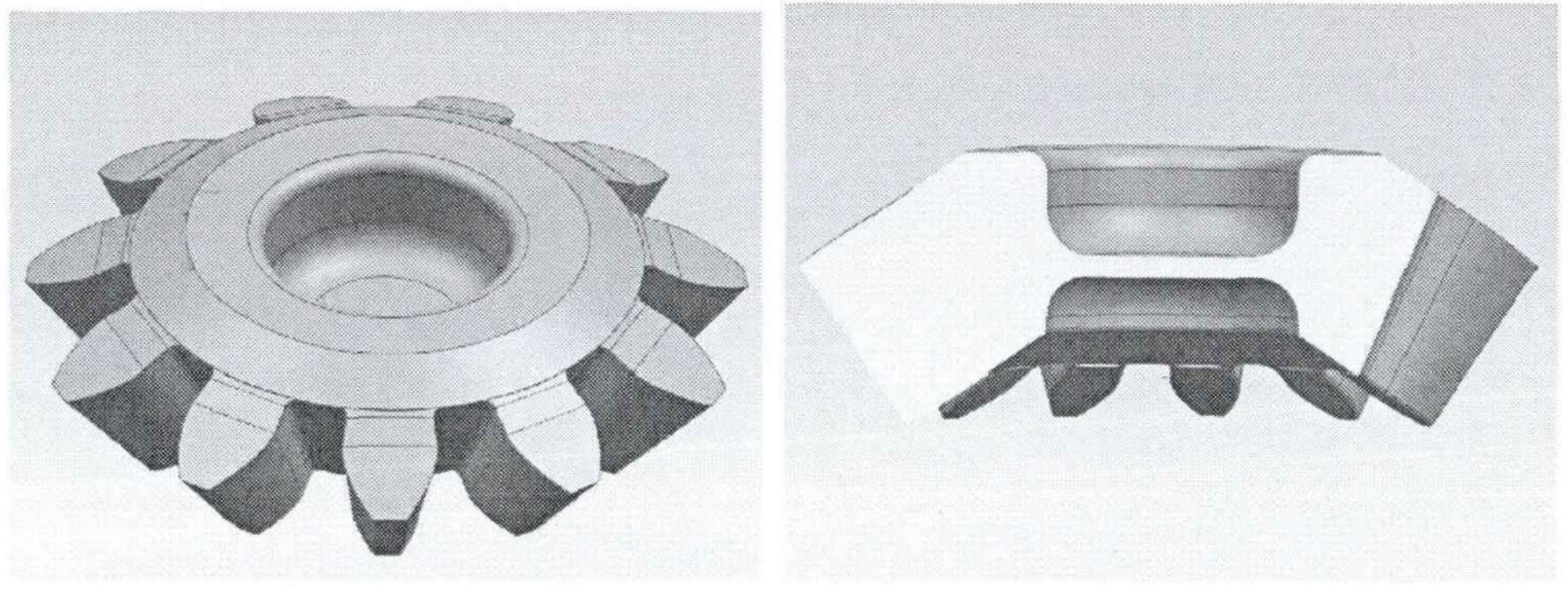
Straight bevel gear have conical tooth profiles and intersecting axes. The teeth are cut straight across the gear’s face and lie on the surface of a cone. The gear teeth mesh at a point along the axis, and the contact between the teeth is along a straight line. This design allows for smooth and efficient power transmission between shafts at various angles.
Applications in Different Transmission Systems:
- Multi-Stage Gear Transmission:
- Straight bevel gear are often used in multi-stage gear transmission systems, where multiple gears with different gear ratios are combined to achieve the desired overall speed reduction or increase.
- In multi-stage transmissions, straight bevel gear can be employed to change the direction of rotation and transmit power between stages.
- These gears help distribute the torque and speed changes across the transmission system while maintaining efficient power transmission.
- Cross Shaft Transmission:
- Cross shaft transmission systems involve the use of multiple shafts intersecting at various angles to transmit power.
- Straight bevel gear are essential in cross shaft transmission setups as they allow power to be transferred between non-parallel shafts while changing the direction of rotation.
- These gears are suitable for applications where space constraints or specific layout requirements dictate the use of intersecting shafts.
- Differential Gear Assemblies:
- Straight bevel gear are commonly used in differential gear assemblies found in vehicles and machinery.
- In a differential, straight bevel gear allow torque to be distributed between the left and right wheels while allowing them to rotate at different speeds during turns.
- The differential’s role is critical for smooth vehicle handling and tire wear.
- Milling and Cutting Machines:
- Straight bevel gear are often used in milling machines and cutting tools to transmit motion between the motor and the cutting head.
- These gears ensure precise rotational motion while changing the direction of rotation.
- Industrial Machinery:
- Straight bevel gear find application in various industrial machinery setups where intersecting shafts need to transmit power efficiently and change the direction of rotation.
- Examples include conveyor systems, printing presses, and textile machinery.
Straight bevel gear play a versatile role in gear transmission systems, enabling efficient power transmission and direction changes between intersecting shafts. Their configuration and design make them suitable for multi-stage gear transmissions, cross shaft transmissions, differential assemblies, and various industrial applications where precise motion transfer is essential.
Chapter 3: The Working Principle of Straight Bevel Gear
The working principle of straight bevel gear involves the meshing of two conical gears with intersecting axes to transmit rotational motion and power. Here’s a breakdown of key concepts:
- Meshing Principle:
- Straight bevel gear consist of two gears, one with teeth on the outer surface (pinion) and the other with teeth on the inner surface (gear).
- When the gears are engaged, their teeth mesh and roll along each other’s surfaces, transferring motion and torque between the shafts.
- Tooth Surface Contact:
- The contact between straight bevel gear teeth occurs along straight lines, similar to spur gears, but on a conical surface.
- Proper tooth geometry ensures smooth and consistent contact as the gears rotate.
- Gear Transmission Ratio:
- The gear transmission ratio, also known as the gear ratio, defines the relationship between the rotational speeds of the input and output shafts.
- For straight bevel gear, the gear ratio is determined by the number of teeth on the pinion (smaller gear) and the gear (larger gear). The ratio can be calculated using the formula: Gear Ratio = Teeth on Gear / Teeth on Pinion.
- Power Transmission:
- As the pinion rotates, its teeth engage the teeth on the gear, causing the gear to rotate in the opposite direction.
- Torque is transmitted from the input (pinion) shaft to the output (gear) shaft, resulting in the transfer of power.
Applications of Gears in Different Transmission Systems:
- Spur Gears:
- Spur gears have parallel shafts and teeth that are parallel to the gear axis.
- They are used in applications where motion needs to be transferred between parallel shafts, such as conveyor systems, automotive transmissions, and clock mechanisms.
- Helical Gears:
- Helical gears have angled teeth that are positioned at an angle to the gear axis.
- They provide smoother and quieter operation compared to spur gears and are commonly used in automotive transmissions, industrial machinery, and power tools.
- Bevel Gears:
- Bevel gears have conical teeth and are used for transmitting motion between intersecting shafts.
- Straight bevel gears change the direction of rotation and are found in differential assemblies, machine tools, and cross shaft transmissions.
- Spiral bevel gears offer smoother engagement and are used in applications requiring high torque transmission, such as automotive differentials and heavy machinery.
- Worm Gears:
- Worm gears consist of a worm (screw-like gear) and a worm wheel (helical gear).
- They are used to achieve high gear reduction ratios and are commonly found in applications like steering mechanisms, conveyor systems, and lifting equipment.
- Planetary Gears:
- Planetary gears use a central sun gear, planet gears, and a ring gear to achieve versatile gear ratios.
- They are employed in automatic transmissions, robotics, and various industrial machinery where compactness and high torque transmission are required.
- Epicyclic Gears (Sun and Planet Gears):
- Epicyclic gears involve planet gears rotating around a central sun gear or within a ring gear.
- They are used in automatic transmissions, differential mechanisms, and power transmission systems where multiple speed ratios and torque distribution are essential.
These different types of gears are essential components in various transmission systems, enabling motion transfer, speed regulation, torque amplification, and direction changes in a wide range of mechanical applications.
Chapter 4: The Manufacturing Process of Straight Bevel Gear
The manufacturing process of straight bevel gear involves several steps to ensure the accurate production of high-quality gears. Here’s an overview of the process, including gear processing methods, heat treatment, surface treatment, and quality assurance measures:
1. Gear Processing Methods:
- Gear Blank Preparation: Start with a suitable gear blank made from a high-quality steel or alloy. The blank is usually forged or machined to the approximate shape of the gear.
- Gear Cutting: Use specialized gear-cutting methods, such as milling, hobbing, shaping, or broaching, to accurately cut the gear teeth. The choice of method depends on factors like gear size, tooth profile, and production volume.
- Tooth Grinding (Optional): For high-precision gears, tooth grinding may be employed to achieve tight tolerances and improve tooth surface finish.
2. Heat Treatment:
- Carburizing: Carburizing is a common heat treatment method used to enhance the surface hardness of gears. The gear is heated in a carbon-rich environment, causing carbon to diffuse into the surface, creating a hardened layer.
- Quenching and Tempering: After carburizing, the gear is quenched to rapidly cool and harden the surface. Tempering follows to relieve internal stresses and achieve the desired balance of hardness and toughness.
3. Machining and Finishing:
- Machining: After heat treatment, the gear may undergo secondary machining operations to achieve precise dimensions, tolerances, and gear fit.
- Finishing Operations: These include grinding, lapping, or honing to further improve gear accuracy, surface finish, and noise characteristics.
4. Surface Treatment:
- Shot Peening: Shot peening is used to improve gear fatigue resistance by inducing compressive stresses on the gear surface. This enhances gear durability and lifespan.
- Surface Coatings: Applying coatings like nitriding or DLC (Diamond-Like Carbon) can improve wear resistance, reduce friction, and enhance overall gear performance.
5. Quality Assurance Measures:
- Metrology and Inspection: Utilize advanced metrology tools, such as coordinate measuring machines (CMMs), gear analyzers, and profile testers, to measure gear dimensions, tooth profiles, and other critical parameters.
- Gear Testing: Perform tests like backlash measurement, runout testing, tooth contact pattern analysis, and noise testing to verify gear performance and quality.
- Material and Heat Treatment Control: Ensure the use of high-quality materials and closely monitor heat treatment processes to achieve desired hardness, toughness, and material properties.
- Process Control: Implement process control techniques to maintain consistent gear quality throughout manufacturing.
- Documentation and Traceability: Maintain comprehensive documentation and traceability of materials, processes, and quality control steps to ensure accountability and facilitate quality improvement.
6. Assembly and System Integration:
- Ensure proper gear assembly and alignment in the final system to achieve smooth and efficient power transmission.
- Perform thorough testing and validation of the entire system to ensure reliable and accurate gear operation within the intended application.
By following these manufacturing steps and quality assurance measures, manufacturers can produce straight bevel gear that meet tight tolerances, exhibit superior surface finish, and deliver reliable performance in various applications.
Chapter 5: Standards and Specifications for Straight Bevel Gear
Relevant standards and specifications play a crucial role in ensuring the design, manufacturing, and testing of straight bevel gear meet industry-accepted quality and performance criteria. Here are some important standards and specifications related to straight bevel gear:
1. ISO Standards:
- ISO 23509: This standard specifies the geometry, tolerances, and inspection methods for straight bevel gear.
- ISO 10300: Provides guidelines for calculating the strength and durability of bevel gear, including straight bevel gear.
2. AGMA Standards:
- AGMA 929-A06: This standard covers the calculation of the load capacity of straight bevel gear.
- AGMA 2015-1-A01: Specifies information on design, rating, and application practices for bevel gear, including straight bevel gear.
- AGMA 6002-B93: Outlines the specifications for straight bevel gear, including gear tooth proportions, tolerances, and inspection methods.
3. DIN Standards:
- DIN 3962-2: Provides information on the calculation and design of bevel gear, including straight bevel gear.
- DIN 3971: Specifies gear terminology and definitions, including those related to bevel gear.
4. ANSI Standards:
- ANSI/AGMA 2003-B97: Covers the design, specification, and inspection of straight bevel gear.
- ANSI/AGMA 6011-C93: Provides information on gear tooth accuracy and tolerances, applicable to straight bevel gear.
5. JIS Standards:
- JIS B 1702-1: Defines gear accuracy grades for straight bevel gear in terms of tooth profile, helix, and pitch deviations.
6. Quality Management Standards:
- ISO 9001: General quality management system standards that provide guidelines for ensuring consistent quality throughout the design, manufacturing, and testing processes.
- ISO 17025: Specifies requirements for testing and calibration laboratories to ensure accurate and reliable results.
7. NIST (National Institute of Standards and Technology):
- Provides guidelines and resources for gear metrology, including testing and inspection procedures.
8. Manufacturer-Specific Standards:
- Some industries or manufacturers may have their own internal standards and specifications for straight bevel gear. These may include specific requirements for materials, heat treatment, testing, and quality control.
9. Industry-Specific Standards:
- Depending on the application, specific industries (such as automotive, aerospace, or industrial machinery) may have additional standards and specifications that apply to straight bevel gear.
Manufacturers, designers, and engineers involved in the design, manufacturing, and testing of straight bevel gear should refer to these standards and specifications to ensure compliance with best practices and to achieve consistent quality, reliability, and performance. Adhering to recognized standards helps ensure that straight bevel gear meet the highest industry standards and perform effectively in their intended applications.
Chapter 6: The Application of Straight Bevel Gear in Different Fields
Straight bevel gear find application in various industries due to their ability to change the direction of rotation and transmit power between intersecting shafts. Here are some common fields where straight bevel gear are used:
- Automotive Industry:
- Differential assemblies: Straight bevel gear are crucial components in automotive differentials, enabling torque distribution between wheels while allowing for smooth turns.
- Transmission systems: They are used in manual transmissions, providing gear reduction and direction change.
- Engineering Machinery:
- Construction equipment: Straight bevel gear are used in heavy machinery such as excavators, bulldozers, and cranes to transmit power from the engine to various components.
- Agricultural machinery: Tractors and other agricultural equipment use straight bevel gear for power transmission and direction change.
- Aerospace Industry:
- Helicopter and aircraft transmission systems: Straight bevel gear are used to change the direction of rotation and transfer power in helicopter and aircraft transmission systems.
- Industrial Machinery:
- Machine tools: Straight bevel gear are employed in milling machines, lathes, and other machine tools to transfer motion and power between intersecting shafts.
- Textile machinery: They are used in spinning and weaving machines to control the motion of various components.
- Marine Industry:
- Marine propulsion systems: Straight bevel gear are used in marine engines and propulsion systems to transfer power between engines and propellers.
Requirements for Gear Performance in Different Application Fields:
The performance requirements for straight bevel gear vary depending on the specific application field. Here are some key performance considerations in different industries:
- Automotive Industry:
- Durability and wear resistance: Gears must withstand varying loads and conditions to ensure long service life.
- Noise and vibration control: Automotive gears should operate quietly to ensure a comfortable driving experience.
- Engineering Machinery:
- Heavy-duty capability: Gears used in construction and mining equipment must handle high loads and tough operating conditions.
- Reliability: Gears should have high reliability to minimize downtime and maintenance costs.
- Aerospace Industry:
- Lightweight design: Aerospace gears require lightweight materials and precise manufacturing to meet weight restrictions and ensure safety.
- High-performance materials: Aerospace gears often require advanced materials to withstand extreme temperature variations and loads.
- Industrial Machinery:
- Precision and accuracy: Gears used in machine tools should have precise tooth profiles to ensure accurate motion control.
- Efficiency: Industrial gears need to minimize power losses to ensure efficient operation.
- Marine Industry:
- Corrosion resistance: Marine gears should be resistant to saltwater corrosion.
- Sealing and protection: Gears need effective sealing to prevent water ingress and ensure reliable operation.
In all these fields, gear designers and manufacturers need to consider factors such as load, speed, torque, operating environment, and material selection to ensure that straight bevel gear meet the specific performance requirements of the application. Proper design, manufacturing, and testing processes are essential to ensure the reliability, durability, and efficiency of straight bevel gear in various industries.
Chapter 7: New Technologies in the Field of Straight Bevel Gear
New technologies and trends are reshaping the field of straight bevel gear, enhancing design, manufacturing, and performance. Here’s an overview of some of these technologies and their impact:
1. Digital Design and Simulation:
- Computer-Aided Design (CAD): CAD software enables precise 3D modeling of gear systems, facilitating accurate design, visualization, and analysis of straight bevel gear.
- Finite Element Analysis (FEA): FEA tools simulate gear behavior, stress distribution, and deformation under different operating conditions, aiding in optimizing gear designs for performance and reliability.
- Virtual Prototyping: Digital design and simulation allow engineers to test and refine gear designs before physical manufacturing, reducing development time and costs.
2. Additive Manufacturing (3D Printing):
- Rapid Prototyping: Additive manufacturing allows for the rapid production of prototypes and small batches of gears, enabling iterative design improvements and faster development cycles.
- Complex Geometries: 3D printing can create intricate gear geometries that were previously challenging or impossible to manufacture using traditional methods.
- Customization: Additive manufacturing enables customized gear designs tailored to specific applications, optimizing performance and efficiency.
3. Intelligent Monitoring and Predictive Maintenance:
- Condition Monitoring: Sensors and IoT technologies can monitor gear performance, temperature, vibration, and other parameters in real time, enabling early detection of anomalies and potential failures.
- Predictive Maintenance: Data-driven analytics and machine learning algorithms can predict gear health and remaining lifespan, optimizing maintenance schedules and minimizing downtime.
4. Advanced Materials and Surface Treatments:
- Advanced Alloys: New materials with improved strength, wear resistance, and fatigue properties enhance gear performance in demanding applications.
- Surface Coatings: Innovative coatings like DLC (Diamond-Like Carbon) can improve gear surface properties, reducing friction and wear.
5. Digital Twin Technology:
- Digital Twin: A digital representation of a physical gear system, the digital twin allows real-time monitoring, simulation, and analysis of gear performance in a virtual environment.
- Performance Optimization: Digital twins help engineers analyze different operating scenarios, optimize gear parameters, and predict performance under varying conditions.
6. Automation and Robotics:
- Automated Manufacturing: Robotics and automation enhance gear manufacturing precision, consistency, and efficiency, reducing human error.
- Lights-Out Manufacturing: Advanced automation allows for unmanned and continuous gear production, optimizing resource utilization.
7. Advanced Metrology and Inspection:
- Non-Destructive Testing (NDT): Advanced NDT techniques like 3D scanning and computed tomography (CT) enable comprehensive inspection of gear components for defects and irregularities.
- High-Precision Metrology: Cutting-edge metrology tools ensure accurate measurement and verification of gear dimensions, tooth profiles, and surface quality.
These new technologies and trends offer opportunities to enhance the design, manufacturing, and performance of straight bevel gear. They enable greater customization, improved accuracy, real-time monitoring, and optimized maintenance strategies, ultimately leading to more efficient and reliable gear systems in various industries.