
I treat the straight bevel gear as a precision mechanical element whose big-end tooth thickness must be known from the actual spherical geometry rather than from an approximate planar substitute. My first-person objective is to build an exact calculation route for the straight bevel gear big-end tooth thickness by deriving the spherical involute of the straight bevel gear tooth surface, expressing that involute in a coordinate system adapted to the tooth, and then extracting both arc thickness and chord thickness. I use the same geometric foundation for the entire straight bevel gear tooth, so the method can be applied at the addendum, at the pitch cone, at the dedendum, or at any intermediate cone angle. The result is a calculation procedure that is more faithful to the straight bevel gear than the traditional equivalent gear method, especially when the cone angle and module place the tooth in a region where planar approximation error becomes noticeable.
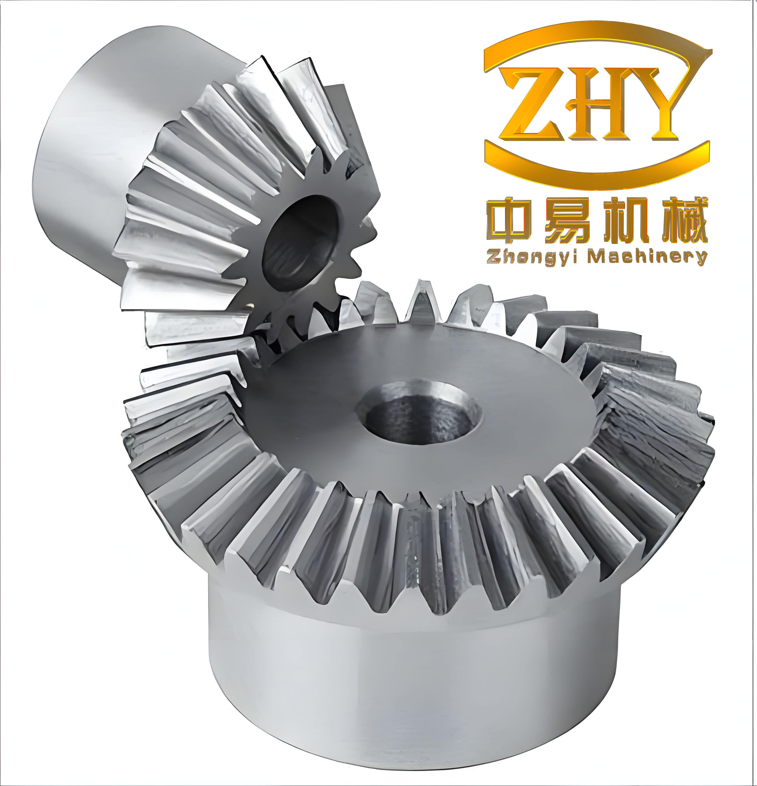
Motivation. In my design and manufacturing work, the straight bevel gear is one of the most common intersecting-axis transmissions. Its big end is the reference region. The straight bevel gear tooth thickness at the big end controls backlash, contact position, cutting depth, inspection dimensions, and the final meshing quality. If I calculate this straight bevel gear tooth thickness with a planar equivalent gear, I am replacing a spherical involute with a cylindrical involute and then scaling it. That substitution is convenient, but it is not exact. The error may be small for some straight bevel gear proportions, yet it is not zero. When I need a precise straight bevel gear manufacturing parameter, a non-zero methodological error is unacceptable. I therefore derive the exact straight bevel gear big-end tooth thickness from the generation principle of the straight bevel gear tooth surface.
Geometric idea. My starting point is the standard generation model of a straight bevel gear. A plane rolls without sliding on a base cone whose apex coincides with the straight bevel gear apex. The straight bevel gear tooth surface is the envelope or swept surface generated by a line in the rolling plane. The intersection of that tooth surface with a sphere centered at the apex is a spherical involute. This spherical involute is the true big-end tooth profile of the straight bevel gear. I do not replace it by a planar involute. I represent it parametrically and then compute the distance between the two flanks at any chosen cone angle.
For the straight bevel gear, I define the following symbols.
| Symbol | Meaning | Role in the straight bevel gear calculation |
|---|---|---|
| R | Cone distance, also the spherical radius | Defines the sphere on which the big-end profile lies |
| m | Big-end module | Sets the pitch tooth thickness scale |
| z | Number of teeth | Used through the equivalent gear comparison |
| delta | Pitch cone angle | Locates the pitch point on the spherical involute |
| delta_b | Base cone angle | Controls the spherical involute generation |
| delta_a | Addendum cone angle | Locates the addendum point on the spherical involute |
| alpha | Pressure angle | Used in the classical equivalent gear check |
| phi | Rolling parameter | Parametrizes the spherical involute of the straight bevel gear |
| psi | Auxiliary angle between the radius and the instantaneous axis | Connects the rolling plane to the base cone |
| theta | Auxiliary angular offset | Aligns the straight bevel gear tooth for chord thickness extraction |
Coordinate systems. I use three coordinate systems. The fixed system S has its origin at the straight bevel gear apex. Its z-axis is the straight bevel gear axis, positive from the apex toward the big end. Its x-axis is aligned with the bottom radius that corresponds to the starting point of the spherical involute. Its y-axis follows the right-hand rule. The moving system S1 also has its origin at the apex, but its z1-axis is the instantaneous rolling axis. Its x1-axis lies in the rolling plane and is perpendicular to z1. The auxiliary system S2 is used at the end to rotate the spherical involute so that the chord thickness of the straight bevel gear appears directly as twice the absolute y-coordinate.
In the moving system S1, a point on the spherical involute is described by
$$
x_1 = R\sin\psi
$$
$$
y_1 = 0
$$
$$
z_1 = R\cos\psi
$$
Because the rolling plane rolls without sliding on the base cone, the arc length on the rolling plane equals the arc length on the base cone. This gives the fundamental relation
$$
\psi R = \phi R\sin\delta_b
$$
so that
$$
\psi = \phi\sin\delta_b
$$
Here phi is the rolling parameter of the straight bevel gear spherical involute. Substituting this relation into the moving coordinates gives
$$
x_1 = R\sin(\phi\sin\delta_b)
$$
$$
y_1 = 0
$$
$$
z_1 = R\cos(\phi\sin\delta_b)
$$
Transformation to the fixed system. I transform from S1 to S through two elementary transformations. The first accounts for the inclination of the base cone, and the second accounts for the rolling angle. In homogeneous form, I write
$$
\begin{bmatrix}
x\\
y\\
z\\
1
\end{bmatrix}
=
M_1 M_2
\begin{bmatrix}
x_1\\
y_1\\
z_1\\
1
\end{bmatrix}
$$
with
$$
M_1 =
\begin{bmatrix}
\sin\phi & \cos\phi & 0 & 0\\
-\cos\phi & \sin\phi & 0 & 0\\
0 & 0 & 1 & 0\\
0 & 0 & 0 & 1
\end{bmatrix}
$$
and
$$
M_2 =
\begin{bmatrix}
1 & 0 & 0 & 0\\
0 & \cos\delta_b & \sin\delta_b & 0\\
0 & -\sin\delta_b & \cos\delta_b & 0\\
0 & 0 & 0 & 1
\end{bmatrix}
$$
Carrying out the multiplication gives the exact parametric equations of the straight bevel gear big-end spherical involute in the fixed system:
$$
Q_x(\phi)
=
R\left[
\cos(\phi\sin\delta_b)\sin\delta_b\cos\phi
+
\sin(\phi\sin\delta_b)\sin\phi
\right]
$$
$$
Q_y(\phi)
=
R\left[
\cos(\phi\sin\delta_b)\sin\delta_b\sin\phi
–
\sin(\phi\sin\delta_b)\cos\phi
\right]
$$
$$
Q_z(\phi)
=
R\cos(\phi\sin\delta_b)\cos\delta_b
$$
These three equations are the core of my exact straight bevel gear tooth thickness method. They describe the true spherical involute of the straight bevel gear, not a planar approximation. For a point on the addendum cone, I require
$$
Q_z(\phi_a) = R\cos\delta_a
$$
so that
$$
\phi_a
=
\frac{
\arccos\left(
\frac{\cos\delta_a}{\cos\delta_b}
\right)
}{
\sin\delta_b
}
$$
The full range of the rolling parameter for the straight bevel gear tooth profile is
$$
0 \le \phi \le
\frac{
\arccos\left(
\frac{\cos\delta_a}{\cos\delta_b}
\right)
}{
\sin\delta_b
}
$$
For any intermediate cone angle delta_n on the straight bevel gear, the corresponding rolling parameter is
$$
\phi_n
=
\frac{
\arccos\left(
\frac{\cos\delta_n}{\cos\delta_b}
\right)
}{
\sin\delta_b
}
$$
This single relation lets me move along the straight bevel gear tooth from the base cone to the addendum cone without changing the mathematical model.
Pitch point of the straight bevel gear. The pitch cone angle of the straight bevel gear is delta. At the pitch point, the corresponding rolling parameter is
$$
\phi_p
=
\frac{
\arccos\left(
\frac{\cos\delta}{\cos\delta_b}
\right)
}{
\sin\delta_b
}
$$
At this pitch point, the projected radius in the xy-plane is
$$
r_p = R\sin\delta
$$
I define theta_1 as the angular distance between the starting radius of the spherical involute and the pitch radius of the straight bevel gear. From the dot product of the starting vector and the pitch vector,
$$
\theta_1
=
\arccos\left(
\frac{
Q_x(\phi_p)
}{
R\sin\delta
}
\right)
$$
The pitch arc thickness of the straight bevel gear is half the circular pitch, so the half-thickness at the pitch cone is
$$
\frac{\pi m}{4}
$$
Because this half-thickness is measured along the pitch circle on the sphere, I write
$$
\frac{\pi m}{4}
=
R\sin\delta \cdot \theta_2
$$
and therefore
$$
\theta_2
=
\frac{\pi m}{4R\sin\delta}
$$
The total angular offset that aligns the straight bevel gear tooth for chord thickness calculation is
$$
\theta = \theta_1 + \theta_2
$$
Exact arc thickness. For any cone angle delta_n on the straight bevel gear, I first compute the corresponding involute angle
$$
\theta_n
=
\arccos\left(
\frac{
Q_x(\phi_n)
}{
R\sin\delta_n
}
\right)
$$
Then the exact arc thickness of the straight bevel gear at that cone angle is
$$
S_{arc}(\delta_n)
=
2(\theta – \theta_n)R\sin\delta_n
$$
At the pitch cone, delta_n equals delta, theta_n equals theta_1, and the formula reduces to
$$
S_{arc}(\delta)
=
2(\theta_1 + \theta_2 – \theta_1)R\sin\delta
=
2\theta_2 R\sin\delta
=
\frac{\pi m}{2}
$$
This is exactly the standard pitch arc thickness of the straight bevel gear. The fact that the exact spherical formula reproduces the known pitch value gives me confidence that the derivation is consistent.
At the addendum cone, delta_n equals delta_a, and the exact arc thickness of the straight bevel gear is
$$
S_{arc}(\delta_a)
=
2(\theta – \theta_a)R\sin\delta_a
$$
where
$$
\theta_a
=
\arccos\left(
\frac{
Q_x(\phi_a)
}{
R\sin\delta_a
}
\right)
$$
Exact chord thickness. To obtain the chord thickness of the straight bevel gear, I rotate the fixed system by the angle theta. The new coordinates are
$$
x_2 = Q_x(\phi)\cos\theta + Q_y(\phi)\sin\theta
$$
$$
y_2 = -Q_x(\phi)\sin\theta + Q_y(\phi)\cos\theta
$$
$$
z_2 = Q_z(\phi)
$$
The straight bevel gear chord thickness at the chosen cone angle is twice the absolute value of y2:
$$
S_{chord}(\delta_n)
=
2\left|
Q_y(\phi_n)\cos\theta
–
Q_x(\phi_n)\sin\theta
\right|
$$
Because the projected involute has the form
$$
Q_x(\phi_n) = R\sin\delta_n \cos\theta_n
$$
$$
Q_y(\phi_n) = R\sin\delta_n \sin\theta_n
$$
I can also write the exact chord thickness as
$$
S_{chord}(\delta_n)
=
2R\sin\delta_n
\left|
\sin(\theta_n – \theta)
\right|
=
2R\sin\delta_n
\left|
\sin(\theta – \theta_n)
\right|
$$
This form is compact and useful for sensitivity studies. It shows directly that the chord thickness of the straight bevel gear differs from the arc thickness by the usual sine-versus-angle difference. For small angular thickness, the difference is very small, but for a precise straight bevel gear calculation I keep the exact sine form.
Calculation algorithm. My exact straight bevel gear tooth thickness procedure can be summarized as follows.
| Step | Operation | Output |
|---|---|---|
| 1 | Input R, m, delta, delta_b, delta_a | Basic straight bevel gear geometry |
| 2 | Compute phi_p from the pitch cone angle | Pitch rolling parameter |
| 3 | Compute Qx and Qy at phi_p | Pitch point on the spherical involute |
| 4 | Compute theta_1 | Starting angle to pitch radius |
| 5 | Compute theta_2 from m, R, delta | Half pitch thickness angle |
| 6 | Set theta = theta_1 + theta_2 | Alignment angle for chord thickness |
| 7 | Choose delta_n | Target cone angle on the straight bevel gear |
| 8 | Compute phi_n from delta_n | Target rolling parameter |
| 9 | Compute Qx, Qy, Qz at phi_n | Target point on the spherical involute |
| 10 | Compute theta_n | Target involute angle |
| 11 | Compute S_arc and S_chord | Exact straight bevel gear thickness |
Worked example for a straight bevel gear. I choose a straight bevel gear with the following parameters. The values are representative of a small straight bevel gear and are sufficient to reveal the difference between the exact spherical method and the traditional equivalent gear method.
| Parameter | Symbol | Value |
|---|---|---|
| Module | m | 3 mm |
| Cone distance | R | 53 mm |
| Number of teeth | z | 25 |
| Addendum cone angle | delta_a | 48 degrees 15 minutes |
| Pitch cone angle | delta | 45 degrees |
| Base cone angle | delta_b | 41 degrees 38 minutes |
| Pressure angle | alpha | 20 degrees |
I first compute the rolling parameter at the addendum cone:
$$
\phi_a
=
\frac{
\arccos\left(
\frac{\cos 48^\circ 15′}{\cos 41^\circ 38′}
\right)
}{
\sin 41^\circ 38′
}
=
0.710
$$
Next I compute the rolling parameter at the pitch cone:
$$
\phi_p
=
\frac{
\arccos\left(
\frac{\cos 45^\circ}{\cos 41^\circ 38′}
\right)
}{
\sin 41^\circ 38′
}
=
0.497
$$
Using the pitch point, I obtain
$$
\theta_1 = 0.020
$$
and
$$
\theta_2
=
\frac{
3\pi
}{
4 \times 53 \times \sin 45^\circ
}
=
0.063
$$
Therefore,
$$
\theta = \theta_1 + \theta_2 = 0.083
$$
At the addendum cone, the involute angle of the straight bevel gear is
$$
\theta_a = 0.055
$$
The addendum arc thickness of the straight bevel gear is
$$
S_{arc}(\delta_a)
=
2(0.083 – 0.055)
\times 53
\times \sin 48^\circ 15′
=
2.214 \text{ mm}
$$
The addendum chord thickness of the straight bevel gear is
$$
S_{chord}(\delta_a)
=
2.205 \text{ mm}
$$
These values are the exact spherical results for this straight bevel gear.
| Quantity | Value | Unit |
|---|---|---|
| Addendum rolling parameter phi_a | 0.710 | rad |
| Pitch rolling parameter phi_p | 0.497 | rad |
| Angular offset theta_1 | 0.020 | rad |
| Half pitch angle theta_2 | 0.063 | rad |
| Total angular offset theta | 0.083 | rad |
| Addendum involute angle theta_a | 0.055 | rad |
| Exact addendum arc thickness | 2.214 | mm |
| Exact addendum chord thickness | 2.205 | mm |
Comparison with the equivalent gear method. The traditional calculation replaces the straight bevel gear big end by a virtual cylindrical gear. For this straight bevel gear, the equivalent number of teeth is
$$
z_v
=
\frac{z}{\cos\delta}
=
\frac{25}{\cos 45^\circ}
=
35.355
$$
The equivalent pitch radius is
$$
r
=
\frac{1}{2}m z_v
=
53.033 \text{ mm}
$$
The equivalent addendum radius is
$$
r_a
=
\frac{1}{2}m z_v + h_a^* m
=
56.033 \text{ mm}
$$
The base radius is
$$
r_b = r\cos\alpha = 49.834 \text{ mm}
$$
The addendum pressure angle is
$$
\alpha_a
=
\arccos\left(
\frac{r_b}{r_a}
\right)
=
0.475 \text{ rad}
$$
The involute functions are
$$
\operatorname{inv}\alpha_a
=
\tan\alpha_a – \alpha_a
=
0.039
$$
$$
\operatorname{inv}\alpha
=
\tan\alpha – \alpha
=
0.015
$$
The equivalent gear pitch thickness is
$$
s = \frac{1}{2}\pi m = 4.712 \text{ mm}
$$
The traditional addendum arc thickness of the straight bevel gear is then
$$
s_{arc,eq}
=
\frac{r_a}{r}s
–
2r_a(\operatorname{inv}\alpha_a – \operatorname{inv}\alpha)
=
2.256 \text{ mm}
$$
The difference between the equivalent gear value and my exact spherical value is
$$
\Delta
=
s_{arc,eq}
–
S_{arc}(\delta_a)
=
2.256 – 2.214
=
0.042 \text{ mm}
$$
| Method | Addendum arc thickness (mm) | Difference from exact (mm) |
|---|---|---|
| Exact spherical involute method for the straight bevel gear | 2.214 | 0.000 |
| Traditional equivalent gear method | 2.256 | +0.042 |
The traditional method overestimates the straight bevel gear addendum arc thickness in this example. The magnitude of the error is not enormous, but it is systematic. In a precision straight bevel gear process, a 0.042 mm thickness error can change backlash and contact pattern. Because my method uses the actual spherical involute, it removes this systematic error.
Why the equivalent gear method differs. The equivalent gear method maps the straight bevel gear big end to a plane. The mapping preserves the pitch radius and the module, but it does not preserve the spherical metric. The spherical involute has a changing geodesic curvature as the cone angle changes. The planar involute has a constant generating geometry in the plane. The mismatch appears as an angular error in the tooth thickness. The error is a function of the cone angle, the base cone angle, the module, and the cone distance. For a straight bevel gear with a small cone angle or a large module relative to the cone distance, the error grows. For a straight bevel gear with a very large cone distance, the error tends to become smaller because the sphere locally approaches a plane. My method remains exact over the whole range.
Arc thickness versus chord thickness. I keep both measures because they serve different purposes. The arc thickness is the geodesic length along the sphere at a given cone angle. It is the natural design quantity for the straight bevel gear because it follows the spherical pitch surface. The chord thickness is the straight-line distance between the two flanks at the same cone angle. It is the quantity that a span gauge, a measuring pin, or some inspection setups can approximate. The two are related by
$$
S_{arc}(\delta_n)
=
2R\sin\delta_n(\theta – \theta_n)
$$
and
$$
S_{chord}(\delta_n)
=
2R\sin\delta_n
\left|
\sin(\theta – \theta_n)
\right|
$$
For the addendum point of the example straight bevel gear, the angular difference is
$$
\theta – \theta_a = 0.083 – 0.055 = 0.028
$$
The arc thickness is proportional to 0.028, while the chord thickness is proportional to sin(0.028). The numerical difference is small, but I retain the exact trigonometric form for precision. In a straight bevel gear with a thicker tooth or a smaller cone distance, the difference can become more significant.
Generalization along the straight bevel gear tooth. My equations are not limited to the addendum. I can select any delta_n between the base cone angle and the addendum cone angle. The same steps apply. I compute phi_n, Qx, Qy, Qz, theta_n, and then the thickness. This is useful for straight bevel gear design because the tooth thickness taper from the big end to the small end is not linear in the spherical metric. If I want to know the thickness at a mid-cone section, I do not need to interpolate between the big end and the small end. I evaluate the spherical involute at the exact cone angle of that section.
| Cone angle delta_n | Rolling parameter phi_n | Involute angle theta_n | Arc thickness formula | Chord thickness formula |
|---|---|---|---|---|
| Base cone delta_b | 0 | 0 | 2 theta R sin(delta_b) | 2 R sin(delta_b) sin(theta) |
| Pitch cone delta | phi_p | theta_1 | pi m / 2 | 2 R sin(delta) sin(theta_2) |
| Addendum cone delta_a | phi_a | theta_a | 2(theta – theta_a) R sin(delta_a) | 2 R sin(delta_a) sin(theta – theta_a) |
| Any intermediate delta_n | phi_n | theta_n | 2(theta – theta_n) R sin(delta_n) | 2 R sin(delta_n) sin(theta – theta_n) |
Sensitivity of straight bevel gear tooth thickness. I often need to know how sensitive the big-end straight bevel gear thickness is to small changes in the base cone angle, the cone distance, and the module. The exact formulas allow this directly. The arc thickness at the addendum is
$$
S_{arc}(\delta_a)
=
2(\theta – \theta_a)R\sin\delta_a
$$
If I vary the module, theta_2 changes linearly with m because
$$
\theta_2
=
\frac{\pi m}{4R\sin\delta}
$$
Thus the pitch thickness and, to first order, the addendum thickness respond linearly to module changes. If I vary the cone distance, the angular quantities change because the same physical module occupies a different angular fraction of the sphere. If I vary the base cone angle, the spherical involute itself changes, so the effect is more subtle. The exact method captures all these effects without a linearization assumption.
| Input variation | Primary effect on straight bevel gear thickness | Exact method response |
|---|---|---|
| Module increase | Larger pitch thickness | Theta_2 increases, arc and chord thickness increase |
| Cone distance increase | Smaller angular tooth thickness for the same module | Theta_2 decreases, but R sin(delta) changes |
| Base cone angle increase | Spherical involute shifts | Phi and theta values are recomputed exactly |
| Addendum cone angle increase | Measurement point moves outward | Phi_a and theta_a increase, thickness changes accordingly |
Implementation notes for a straight bevel gear calculation. I recommend evaluating the trigonometric functions in radians. The angles delta, delta_b, and delta_a are usually given in degrees, minutes, and seconds in a straight bevel gear drawing, so I convert them to radians before using the formulas. I compute phi_p and phi_a with the inverse cosine. I then compute Qx and Qy. I use the two-argument arctangent whenever possible for theta_n, because it preserves the correct quadrant and avoids sign ambiguity. The formulas in this article are written with arccosine for clarity, but in a numerical implementation I prefer
$$
\theta_n
=
\operatorname{atan2}
\left(
Q_y(\phi_n),
Q_x(\phi_n)
\right)
$$
This is especially useful when the straight bevel gear tooth is on the opposite flank or when I am computing both flanks of a full tooth. The chord thickness then follows from the absolute sine of the angular difference. The arc thickness follows from the absolute angular difference multiplied by the spherical radius at that cone angle.
Both flanks of the straight bevel gear. A complete straight bevel gear tooth has a left flank and a right flank. The spherical involute derivation above gives one flank. The other flank is obtained by mirroring about the tooth center plane. If I want the full tooth thickness, I compute the angular position of the left flank and the angular position of the right flank at the same cone angle, then take the difference. Because I have an exact parametric expression, I can do this without constructing a planar equivalent gear. The mirror operation is exact and preserves the spherical metric.
For the right flank, I can use the same formulas with a negative rolling parameter or with a reflection of the y-coordinate. In practice, I compute the thickness as
$$
S_{arc}(\delta_n)
=
R\sin\delta_n
\left|
\theta_{right}(\delta_n)
–
\theta_{left}(\delta_n)
\right|
$$
and
$$
S_{chord}(\delta_n)
=
2R\sin\delta_n
\left|
\sin
\left(
\frac{
\theta_{right}(\delta_n)
–
\theta_{left}(\delta_n)
}{2}
\right)
\right|
$$
This pair of equations is a compact summary of the exact straight bevel gear tooth thickness at any cone angle.
Numerical check at the pitch cone. At the pitch cone, I expect the exact straight bevel gear arc thickness to equal half the circular pitch. My calculation gives
$$
S_{arc}(\delta)
=
2(\theta – \theta_1)R\sin\delta
=
2\theta_2 R\sin\delta
=
2
\left(
\frac{\pi m}{4R\sin\delta}
\right)
R\sin\delta
=
\frac{\pi m}{2}
$$
For m = 3 mm, this is
$$
\frac{\pi \times 3}{2}
=
4.712 \text{ mm}
$$
The chord thickness at the pitch cone is
$$
S_{chord}(\delta)
=
2R\sin\delta
\sin\theta_2
=
2 \times 53 \times \sin 45^\circ \times \sin 0.063
=
4.711 \text{ mm}
$$
The two values differ only because the chord is a straight-line approximation of the arc. This is expected and confirms that my exact straight bevel gear formulas behave correctly at the reference point.
| Location on straight bevel gear | Arc thickness (mm) | Chord thickness (mm) |
|---|---|---|
| Pitch cone | 4.712 | 4.711 |
| Addendum cone | 2.214 | 2.205 |
Manufacturing relevance. In my experience, the straight bevel gear big-end tooth thickness is one of the dimensions that most directly affects the assembly. If the straight bevel gear is cut too thick, the gears may bind. If it is cut too thin, the backlash is excessive and the contact pattern moves. The traditional equivalent gear calculation gives a number that is convenient but slightly biased. My exact method gives a number that follows the true spherical involute. When I set the cutter depth or the generating roll for a straight bevel gear, I can use the exact chord thickness for inspection and the exact arc thickness for design. This separation is useful. The arc thickness is the geometric truth along the pitch surface, while the chord thickness is the direct measurable span at the chosen cone angle.
Comparison of formulas. The following table summarizes the contrast between the traditional planar approach and my spherical approach for the straight bevel gear.
| Aspect | Traditional equivalent gear method | Exact spherical involute method for straight bevel gear |
|---|---|---|
| Tooth profile model | Cylindrical involute in a plane | Spherical involute on a sphere |
| Pitch geometry | Equivalent pitch circle | True pitch cone on the sphere |
| Thickness at addendum | Approximate | Exact within the spherical model |
| Effect of cone angle | Indirect through equivalent radius | Direct through delta_n |
| Arc thickness | Planar arc scaled | Geodesic arc on the sphere |
| Chord thickness | Not intrinsic | Exact from rotated coordinates |
| Example error | +0.042 mm | 0.000 mm reference |
Extending to arbitrary cone distance. In the formulas above, R is the cone distance to the big end. If I want to compute the straight bevel gear tooth thickness at a smaller cone distance, I replace R by the local spherical radius R_local. The spherical involute shape is the same, but the absolute thickness scales with the local radius. I can therefore write
$$
S_{arc,local}
=
2(\theta – \theta_n)R_{local}\sin\delta_n
$$
and
$$
S_{chord,local}
=
2R_{local}\sin\delta_n
\left|
\sin(\theta – \theta_n)
\right|
$$
This is useful for a straight bevel gear because the tooth is tapered. The big end is standardized, but the small end and intermediate sections also matter for strength, clearance, and cutting. My method gives those values without a separate approximation.
Numerical stability. The inverse cosine terms are well behaved when the arguments are within the valid range. For a straight bevel gear, the base cone angle is smaller than the pitch cone angle, and the addendum cone angle is larger than the pitch cone angle. Therefore
$$
0 < \frac{\cos\delta_n}{\cos\delta_b} < 1
$$
for the relevant range. The argument of the inverse cosine stays between zero and one. The sine of the base cone angle is positive. The rolling parameter is therefore real and positive. The formulas are numerically stable. If I use atan2 for theta_n, I avoid any quadrant issue. If I use arccosine, I ensure that Qx is positive in the selected coordinate orientation.
Error sources in the straight bevel gear calculation. My method removes the geometric error of the equivalent gear approximation. The remaining error sources are input error and manufacturing error. Input error includes the accuracy of the base cone angle, the cone distance, and the module. Manufacturing error includes cutter profile error, machine setup error, heat treatment distortion, and inspection error. Because my method is exact for the spherical involute, it does not add a systematic thickness bias. This is important for a straight bevel gear because any systematic bias in the calculated thickness propagates directly into the cut depth.
| Error source | Type | Effect on straight bevel gear tooth thickness |
|---|---|---|
| Equivalent gear approximation | Geometric | Removed by the exact spherical method |
| Base cone angle input | Data | Changes phi and theta values |
| Module input | Data | Changes theta_2 linearly |
| Cone distance input | Data | Changes angular scale |
| Cutter profile | Manufacturing | Not removed by geometry |
| Machine setup | Manufacturing | Not removed by geometry |
| Heat treatment | Manufacturing | Not removed by geometry |
Practical recommendation. I recommend that a straight bevel gear design sheet include both the exact arc thickness and the exact chord thickness at the big end. The arc thickness should be used for the geometric definition. The chord thickness should be used for inspection when the available measuring method gives a straight-line span. If the inspection method uses a ball or pin, I convert the measured value to the chord thickness and then compare it with the exact chord value. If the inspection method uses a span over teeth, I compute the corresponding tooth thickness from the same spherical involute. In all cases, the straight bevel gear geometry is represented by the actual spherical involute, not by a planar substitute.
Summary of the exact straight bevel gear equations. For quick reference, I collect the main equations here.
$$
\psi = \phi\sin\delta_b
$$
$$
Q_x(\phi)
=
R\left[
\cos(\phi\sin\delta_b)\sin\delta_b\cos\phi
+
\sin(\phi\sin\delta_b)\sin\phi
\right]
$$
$$
Q_y(\phi)
=
R\left[
\cos(\phi\sin\delta_b)\sin\delta_b\sin\phi
–
\sin(\phi\sin\delta_b)\cos\phi
\right]
$$
$$
Q_z(\phi)
=
R\cos(\phi\sin\delta_b)\cos\delta_b
$$
$$
\phi_n
=
\frac{
\arccos\left(
\frac{\cos\delta_n}{\cos\delta_b}
\right)
}{
\sin\delta_b
}
$$
$$
\theta_n
=
\operatorname{atan2}
\left(
Q_y(\phi_n),
Q_x(\phi_n)
\right)
$$
$$
\theta_1
=
\theta_p
$$
$$
\theta_2
=
\frac{\pi m}{4R\sin\delta}
$$
$$
\theta
=
\theta_1 + \theta_2
$$
$$
S_{arc}(\delta_n)
=
2(\theta – \theta_n)R\sin\delta_n
$$
$$
S_{chord}(\delta_n)
=
2R\sin\delta_n
\left|
\sin(\theta – \theta_n)
\right|
$$
These equations form a complete and exact calculation method for the straight bevel gear big-end tooth thickness. I can evaluate them by hand for a single straight bevel gear or implement them in a spreadsheet, a script, or a CAD system. The method is not restricted to the addendum. It covers the entire spherical involute from the base cone to the addendum cone. It gives the arc thickness and the chord thickness directly. It also provides the angular quantities needed to inspect the straight bevel gear tooth position.
Final assessment. My exact spherical involute method is more accurate than the traditional equivalent gear method for the straight bevel gear. The numerical example shows a systematic difference of 0.042 mm in addendum arc thickness. For a precision straight bevel gear, this difference matters. The method is based on the true generation principle of the straight bevel gear tooth surface, so it does not introduce an avoidable geometric approximation. It uses only standard trigonometric functions and coordinate transformations. It can be applied to the big end, to the small end, and to any intermediate section. It provides both arc thickness and chord thickness. I therefore regard it as a reliable theoretical basis for improving straight bevel gear machining precision, inspection consistency, and design confidence.