
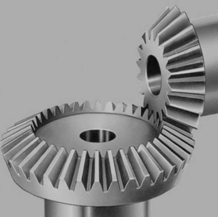
Straight bevel gears are a type of bevel gears that have straight teeth that are cut along the conical surface of the gear. Let’s explore their tooth geometry and operation principles in more detail:
Tooth Geometry:
- Pitch Cone: Straight bevel gears are designed based on the concept of a pitch cone, which is a theoretical cone formed by the imaginary points of contact between mating gears. The pitch cone angle is the angle between the axis of rotation and the generator line of the cone.
- Pitch Point: The pitch point is the point of tangency between the mating gear teeth in the pitch cones. It is the reference point used for determining the gear ratios and tooth contact patterns.
- Pitch Diameter: The pitch diameter is the diameter of the pitch circle on the base section of the gear. It is used to calculate the gear ratio and determine the gear dimensions.
- Module or Diametral Pitch: The module (in the metric system) or diametral pitch (in the imperial system) is a measure of the size of the gear teeth. It specifies the size and spacing of the teeth along the pitch circle.
- Addendum and Dedendum: The addendum is the distance from the pitch circle to the top of the tooth, while the dedendum is the distance from the pitch circle to the bottom of the tooth. These dimensions determine the strength and clearance of the gear teeth.
Operation Principles:
- Meshing Action: When two straight bevel gears with corresponding tooth profiles mesh, the teeth come into contact at the pitch point. The meshing action involves the sliding and rolling of the teeth along the pitch cones.
- Line of Action: The line of action is an imaginary line along which the point of contact between the gear teeth moves during rotation. It is the line perpendicular to the tooth profiles at the pitch point.
- Gear Ratio: The gear ratio of straight bevel gears is determined by the ratio of their numbers of teeth. It defines the speed and torque relationship between the driving and driven gears.
- Contact Pattern: The contact pattern refers to the area of contact between the meshing teeth on the gear faces. Achieving a proper contact pattern is important to ensure smooth operation and even distribution of loads across the tooth surfaces.
- Axial Thrust: Due to the angle of the gear teeth, straight bevel gears generate axial thrust during operation. This thrust can affect the stability of the gear system and may require additional measures, such as thrust bearings, to manage the axial forces.
Understanding the tooth geometry and operation principles of straight bevel gears helps in the design, analysis, and selection of these gears for specific applications. It enables engineers to calculate gear ratios, determine tooth profiles, optimize contact patterns, and ensure efficient and reliable power transmission in gear systems.
Pages: 1 2