
To understand the geometry and operation principles of straight bevel gears, let’s delve into their key elements and working principles.
Geometry of Straight Bevel Gears:
The geometry of straight bevel gears can be described using the following terms:
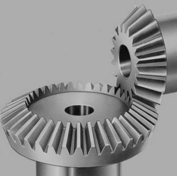
- Pitch Cone: A straight bevel gear is defined by a pair of pitch cones. Each gear has its own pitch cone, which is the imaginary cone that represents the average size and shape of the gear teeth. The apex angle of the pitch cones is usually 90 degrees for straight bevel gears.
- Pitch Point: The point where the pitch cones of two meshing gears intersect is known as the pitch point. It is the point on the gear teeth where the meshing action begins.
- Pitch Circle: The pitch circle is an imaginary circle on the base of the gear teeth that represents the reference diameter of the gear. The teeth are evenly spaced along the pitch circle.
- Pitch Diameter: The pitch diameter is the diameter of the pitch circle. It determines the gear ratio and is related to the number of teeth on the gear.
- Tooth Profile: The teeth of straight bevel gears have a straight shape and taper towards the apex. The tooth profile is designed to ensure smooth engagement and disengagement of the gear teeth.
Operation Principles of Straight Bevel Gears:
The operation of straight bevel gears is based on the principles of meshing and engagement between two gears. Here’s how it works:
- Meshing Action: When two straight bevel gears with the same pitch cone angles are brought together, their teeth mesh with each other. The meshing action occurs as the gear teeth come into contact and engage with one another.
- Torque Transmission: As one gear, known as the driving gear, rotates, its teeth push against the teeth of the other gear, known as the driven gear. This contact and interaction between the teeth allow for the transmission of torque from the driving gear to the driven gear.
- Contact Pattern: The contact pattern refers to the area on the gear teeth where they come into contact during meshing. It is important to ensure that the contact pattern is uniform and properly distributed across the tooth surfaces to ensure smooth operation and minimize wear.
- Axial Thrust: Straight bevel gears generate an axial thrust force due to the angled tooth surfaces. This axial thrust should be properly managed and supported to prevent excessive loading on the gear shafts.
- Gear Ratio and Speed: The gear ratio of straight bevel gears is determined by the number of teeth on the driving and driven gears. By selecting gears with different tooth counts, the rotational speed and torque can be adjusted between the input and output shafts.
- Lubrication and Maintenance: Proper lubrication is essential for the smooth operation and longevity of straight bevel gears. Adequate lubrication ensures reduced friction, wear, and heat generation during gear meshing. Regular maintenance, including gear inspection and lubricant replacement, is necessary to maintain optimal performance.
Understanding the geometry and operation principles of straight bevel gears is crucial for their proper design, selection, and use in various mechanical systems.