
The pursuit of advanced motion transmission has propelled non-circular gears into the spotlight of mechanical design. Their unique capability to facilitate non-uniform motion transfer makes them indispensable in applications ranging from automotive steering systems and automation equipment to agricultural machinery and robotics. While significant research efforts have been dedicated to the design, synthesis, and application of non-circular gears, their manufacturing remains a substantial bottleneck, often limiting widespread adoption. Among various manufacturing methods, gear hobbing stands out as a highly efficient process suitable for the high-volume production of both straight and helical non-circular gears with convex pitch curves. However, the inherent non-circularity of the pitch curve introduces a critical challenge: severe fluctuations in the gear hobbing cutting force.
These force fluctuations compromise the stability of the gear hobbing process, leading to potential issues such as chatter, reduced tool life, and diminished machining accuracy. Consequently, understanding, predicting, and mitigating these fluctuations is paramount for realizing the full potential of non-circular gear hobbing. My research focuses on this very challenge. I delve into the root causes of force variation during the gear hobbing of non-circular gears and propose effective strategies for its suppression. This work is built upon the established principles of unit cutting force calculation and leverages insights from cylindrical gear hobbing research. The core of my analysis hinges on characterizing the cutting force trend through the volume of the undeformed chip generated during a single intermittent cut in the gear hobbing cycle. I develop a methodology to construct a solid model of this undeformed chip specifically for non-circular gear hobbing operations.
To ground this study, I select an oval gear with a large eccentricity as a representative case. I first analyze the force fluctuation characteristics generated by a conventional gear hobbing linkage model where the hob rotates at a constant speed without axial shifting (non-shifting model). This model, while foundational, leads to significant force variations. I then introduce and analyze a novel linkage model for gear hobbing that maintains constant hob speed but incorporates coordinated axial shifting of the hob. This model enforces a constant arc-length increment of engagement between the tool and the workpiece per unit time, a principle crucial for stabilizing the gear hobbing process over the entire revolution. Finally, I investigate the influence of radial depth of cut on the force fluctuation patterns, providing a comprehensive view for optimizing gear hobbing parameters.
Principles and Realization of Non-Circular Gear Hobbing
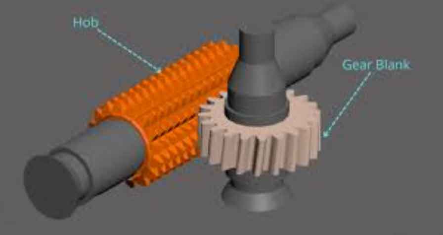
The gear hobbing process for non-circular gears can be conceptually understood as the meshing between a hob (modeled as a worm) and the non-circular gear blank. The machining requires synchronized motion across several axes. As illustrated in the schematic, the essential movements involve the rotation of the hob (B-axis), the rotation of the workpiece (C-axis), the radial infeed motion of the hob relative to the workpiece center (X-axis), and the axial feed of the hob along the gear width (Z-axis). For helical gears, an additional relationship is established to account for the lead.
The fundamental linkage model, which forms the basis for conventional non-circular gear hobbing without hob shifting, is derived from the condition of pure rolling between the pitch curve of the gear and the imaginary rack corresponding to the hob’s projection in the gear’s transverse plane. The governing equations for this model are:
$$
\omega_C = \frac{\sqrt{r^2 + (dr/d\phi)^2}}{r^2} \left( K_C \omega_B \frac{T m_n}{2\cos\beta} + K_Z v_Z \tan\beta \right)
$$
$$
v_X = \frac{dr/d\phi}{r} \left( \omega_B \frac{T m_n}{2\cos\beta} + K_Z v_Z \tan\beta \right)
$$
Where:
- \( \omega_C, \omega_B \) are the angular velocities of the workpiece (C-axis) and hob (B-axis).
- \( v_X, v_Z \) are the linear velocities of the radial (X-axis) and axial (Z-axis) feeds.
- \( r \) and \( \phi \) are the polar radius and angle defining a point on the non-circular pitch curve.
- \( m_n \) is the normal module, \( \beta \) is the helix angle, \( T \) is the number of hob starts.
- \( K_C, K_Z \) are sign coefficients determined by the hand combinations of the hob and gear.
In this basic gear hobbing model, the distance from the pitch point to the hob axis, denoted \( S_Y \), continuously varies. This variation leads to a non-constant velocity of the pitch point along the pitch curve, resulting in a variable arc length of engagement per unit hob revolution. This is a primary source of the fluctuating cutting conditions in non-circular gear hobbing.
Cutting Force Analysis Based on Undeformed Chip Geometry
To analyze the cutting force in gear hobbing, I adopt the well-established Kienzle-Vector empirical force model. This model relates the specific cutting force \( K_s \) to the uncut chip thickness \( h \):
$$
F_c = S \cdot K_s, \quad K_s = \frac{K_c}{h^{u}}
$$
Here, \( F_c \) is the main cutting force, \( S \) is the cross-sectional area of the undeformed chip layer, \( K_c \) is a material constant, and \( u \) is an exponent typically around 0.2-0.3. For a given workpiece material, the cutting force for a specific chip cross-section is dominantly influenced by its area \( S \), with chip thickness \( h \) having a less sensitive, power-law effect. Therefore, the total volume of material removed in a single engagement of a hob tooth provides a strong, positive correlation with the peak cutting force experienced during that cut. This forms the cornerstone of my analysis: I use the volume of the undeformed chip from a single intermittent cut as a robust proxy for identifying the magnitude and location of peak cutting forces in the gear hobbing cycle.
My methodology for obtaining this undeformed chip volume involves a solid modeling-based simulation of the gear hobbing process:
- Hob Tooth Swept Volume: I model the swept volume generated by a single row of hob teeth during one full hob revolution (one intermittent cutting cycle). This accounts for both the hob’s rotation and its axial feed motion.
- Multi-Pass Simulation: To simulate a stable, full-depth cutting condition, I perform a two-pass hobbing simulation. The first pass creates the initial tooth spaces, and the second pass, performed on the pre-cut gear blank, represents the steady-state cutting condition.
- Chip Extraction: For each simulated intermittent cut in the second pass, I perform a Boolean intersection operation between the hob’s swept volume and the gear blank at that specific position. The resulting solid body is the geometric model of the undeformed chip.
- Volume Calculation: The volume of this chip body is computed, providing a quantitative measure for analysis.
To validate this approach, I first applied it to a cylindrical gear hobbing process. The calculated chip volume showed clear periodic fluctuations corresponding to the entry, full engagement, and exit of the hob teeth. The trend of these volume fluctuations matched published data on cutting force variation in cylindrical gear hobbing, confirming the validity of using chip volume as an indicator. The simulation parameters for the primary case study, a large eccentricity oval gear, are summarized below.
| Parameter Category | Value |
|---|---|
| Non-Circular Gear | |
| Number of Teeth | 30 |
| Normal Module (m_n) | 4 mm |
| Helix Angle (β) | 15° (Right Hand) |
| Pitch Curve Type | Second-order Ellipse |
| Pitch Curve Eccentricity | 0.3 |
| Hob | |
| Number of Starts (T) | 1 |
| Type | Archimedean (Right Hand) |
| Outer Diameter | 100 mm |
| Number of Gashes | 8 |
| Process | |
| Axial Feed Rate (v_Z) | 2 mm/workpiece rev |
Force Fluctuation Under the Basic Hobbing Model
Applying the basic (non-shifting) gear hobbing model to the oval gear, I simulated the complete hobbing process and extracted the undeformed chip volume for each intermittent cut over one full revolution of the workpiece. The results reveal a dramatic fluctuation pattern.
The chip volume, and by strong correlation the cutting force, varies significantly with the position on the pitch curve. Crucially, the maximum chip volume occurs not once, but twice per revolution, precisely at the regions near the minor axis of the oval gear—where the pitch curve radius of curvature is largest. The ratio between the maximum and minimum chip volume under this model was found to be as high as 19.3:1. This extreme variation explains the common practical issue observed in the gear hobbing of oval gears for flow meters: pronounced machine vibration and audible chatter when the hob engages the gear near its minor axis. The conventional gear hobbing strategy clearly leads to unstable and demanding cutting conditions at specific phases of the operation.
A Constant Arc-Length Increment Model for Force Suppression
Inspired by constant-surface-speed machining techniques used for cam grinding, I propose a modified linkage model for gear hobbing designed to suppress force fluctuations. The goal is to maintain a constant arc length of engagement between the hob’s reference line and the gear’s pitch curve per unit time. This requires the hob to perform an axial shifting motion (Y-axis movement) in precise coordination with the other axes to keep the instantaneous pitch point at a fixed location on the hob’s reference line.
The required compensatory velocity for the hob shifting axis, \( v_Y \), is derived from the time derivative of the distance \( S_Y \):
$$
v_Y(\phi) = \frac{d}{d\phi}(r \cos \mu) \cdot \frac{d\phi}{dt} = \left[ \frac{(dr/d\phi)^2}{\left[r^2+(dr/d\phi)^2\right]^{1/2}} + \frac{r \frac{d^2r}{d\phi^2} \left[r^2+(dr/d\phi)^2\right] – r (dr/d\phi)^2 – (dr/d\phi)^2 \frac{d^2r}{d\phi^2}}{\left[r^2+(dr/d\phi)^2\right]^{5/2}} \right] \cdot \frac{d\phi}{dt}
$$
Integrating this compensatory motion into the fundamental model yields the enhanced constant arc-length increment gear hobbing linkage model:
$$
\omega_C = \frac{\sqrt{r^2 + (dr/d\phi)^2}}{r^2} \left( K_C \omega_B \frac{T m_n}{2\cos\beta} + K_Z v_Z \tan\beta + v_Y \frac{\cos \lambda}{\cos \beta} \right)
$$
$$
v_X = \frac{dr/d\phi}{r} \left( \omega_B \frac{T m_n}{2\cos\beta} + K_Z v_Z \tan\beta + v_Y \frac{\cos \lambda}{\cos \beta} \right)
$$
$$
v_Y = v_Y(\phi) \frac{\cos \beta}{\cos \lambda}
$$
Where \( \lambda \) is the hob installation angle. This model requires active control of the hob shifting axis (Y-axis) in synchronization with the B, C, X, and Z axes.
Re-running the gear hobbing simulation with this new model produces a markedly different chip volume profile. The peak chip volume is no longer located at the minor axis. The correlation between chip volume and radius of curvature is broken. Instead, the maximum and minimum volumes occur at roughly symmetric positions flanking the major axis region. Most importantly, the ratio of maximum to minimum chip volume is drastically reduced from 19.3 to 6.2—an improvement of approximately 68%. Furthermore, the severe step-change fluctuation observed at the minor axis with the basic model is eliminated, promising significantly improved process stability in gear hobbing.
| Metric | Basic Hobbing Model (Non-Shifting) | Constant Arc-Length Model (With Shifting) |
|---|---|---|
| Peak Force Location | At minor axis (max curvature radius) | Near major axis, on entry side |
| Max/Min Chip Volume Ratio | 19.3 : 1 | 6.2 : 1 |
| Fluctuation Pattern | Severe, with step-changes | Smoothed, more sinusoidal |
| Process Stability | Poor (vibration/chatter likely) | Good (significantly improved) |
Influence of Radial Depth of Cut
In practical gear hobbing, the full tooth depth is not cut in a single pass due to excessive load. A radial infeeding strategy is employed, where the hob is progressively fed in the X-direction in several passes. I investigated how this parameter influences the force fluctuation characteristic, independent of the linkage model.
Simulations were conducted for the basic hobbing model at different radial depths of cut: 25%, 50%, 75%, and 100% of the full tooth depth. The results show that while the absolute magnitude of the chip volume scales nearly proportionally with the depth of cut, the pattern and ratio of fluctuation (max/min volume) remain largely unchanged. This indicates that the cause of fluctuation is geometric and kinematic, linked to the pitch curve shape and the hobbing model, not simply the amount of material being removed.
Therefore, using a smaller radial depth of cut per pass is an effective, practical strategy to directly reduce the absolute magnitude of the peak cutting force encountered during gear hobbing. This allows the process to operate within the stable window of the machine-tool-workpiece system, even if the underlying fluctuation pattern from the basic model persists. For optimal results, this strategy should be combined with the constant arc-length increment linkage model to address both the absolute force magnitude and the relative fluctuation pattern.
Conclusion
This investigation into non-circular gear hobbing has established a clear link between undeformed chip geometry and cutting force fluctuations. The conventional, non-shifting hobbing model leads to severe force variations strongly correlated with pitch curve curvature, causing instability. The proposed constant arc-length increment gear hobbing model, achieved through coordinated hob shifting, fundamentally alters this relationship, suppressing the max/min force ratio by over 68% and smoothing the fluctuation profile. Furthermore, employing a multi-pass strategy with reduced radial depth of cut provides a straightforward method to lower the absolute peak forces. In summary, for stable and precise gear hobbing of non-circular gears, a combined approach is recommended: implementing the kinematic correction of the constant arc-length model to manage the fluctuation pattern, and applying prudent radial infeeding工艺 to control the absolute force levels. This integrated strategy provides a solid theoretical foundation for optimizing non-circular gear hobbing processes, enhancing their viability for high-performance applications.