
In the field of mechanical power transmission, screw gears, particularly worm drives, play a crucial role in applications requiring high reduction ratios and compact design. Among these, the ZC1 circular cylindrical screw gear stands out due to its enhanced load-carrying capacity, improved efficiency, and resistance to wear and pitting. As an engineer focused on advanced manufacturing techniques, I have extensively studied the strength characteristics of ZC1 screw gears to ensure their reliability in demanding operational conditions. This article presents a comprehensive analysis of the strength of ZC1 screw gears, combining analytical methods based on Hertzian contact theory with finite element simulations. The goal is to provide a robust framework for evaluating contact and bending stresses, which are critical for preventing common failure modes like pitting and root wear in screw gears. By integrating formulas, tables, and numerical results, I aim to offer insights that can guide the design and optimization of these screw gears for industrial use.
The ZC1 screw gear, a type of circular cylindrical worm drive, features a concave tooth profile that improves meshing performance and stress distribution. Strength analysis is essential because screw gears often operate under high torque and shock loads, leading to fatigue failures if not properly designed. Traditionally, analytical methods derived from gear meshing theory and Hertzian contact mechanics have been used to estimate stresses. However, these methods can be conservative and may not capture the complex three-dimensional stress states in screw gears. With advancements in computational tools, finite element analysis (FEA) has become a powerful alternative for simulating screw gear behavior under load. In this work, I compare both approaches to validate their accuracy and explore load distribution patterns during meshing. The keyword “screw gears” will be frequently emphasized to highlight the focus on this specific transmission component, as understanding their strength is vital for applications in robotics, automotive systems, and heavy machinery.
To begin, let’s delve into the analytical strength assessment of ZC1 screw gears. The primary failure mechanisms in screw gears are surface pitting due to contact stresses and tooth breakage from bending stresses. For screw gears, the worm wheel, typically made of bronze, is the weaker component and thus the focus of strength calculations. Based on Hertzian theory, the contact stress at the meshing interface can be expressed as:
$$
\sigma_H = Z_E \cdot \sqrt{\frac{F_n}{\rho_n l}}
$$
where $\sigma_H$ is the contact stress, $Z_E$ is the material elasticity coefficient, $F_n$ is the normal force, $\rho_n$ is the equivalent curvature radius in the normal direction, and $l$ is the total contact line length. For screw gears, this formula is adapted to account for the varying contact geometry during meshing. By applying micro-element analysis and assuming uniform stress distribution, the contact stress for ZC1 screw gears can be simplified to a practical engineering formula:
$$
\sigma_H = Z_E Z_\rho \sqrt{\frac{1000 T_2 K_A}{a^3}}
$$
Here, $T_2$ is the output torque (in N·m), $K_A$ is the application factor, $a$ is the center distance (in mm), and $Z_\rho$ is the contact coefficient, which depends on the screw gear geometry. The contact coefficient for cylindrical screw gears can be approximated as $Z_\rho = 2.05 (d_{m1}/a)^{-0.34}$, where $d_{m1}$ is the worm reference diameter. This analytical approach provides a quick estimate but relies on simplifications that may affect accuracy.
Similarly, the bending stress at the tooth root of screw gears is critical for assessing wear resistance. Although the tooth shape of screw gears is complex, an approximate formula based on standard gear calculations can be used:
$$
\sigma_F = \frac{F_{t2} K_A}{m b_2}
$$
where $\sigma_F$ is the bending stress, $F_{t2}$ is the tangential force on the worm wheel, $m$ is the axial module, and $b_2$ is the worm wheel face width. The tangential force relates to torque as $F_{t2} = 2000 T_2 / d_{m2}$, with $d_{m2}$ being the worm wheel reference diameter. Combining these, the bending stress formula for screw gears becomes:
$$
\sigma_F = \frac{2000 T_2 K_A}{(2a’ – d_1) m b_2}
$$
where $a’$ is the meshing center distance (approximately equal to $a$) and $d_1$ is the worm reference diameter. These analytical equations are widely used in design handbooks for screw gears, but they often yield conservative results due to assumptions about load distribution and geometry.
To complement the analytical methods, I developed a finite element model for ZC1 screw gears to simulate stress distributions more accurately. The process began with generating the three-dimensional geometry of the screw gears based on meshing theory. Using parametric programming in ANSYS APDL, I created the worm and worm wheel models with precise tooth profiles. The worm had a concave shape typical of ZC1 screw gears, and the worm wheel was designed to match. The finite element mesh was generated using SOLID64 elements for the bodies, with contact pairs defined using TARGE170 and CONTA174 elements to model the meshing interaction. This approach allowed for nonlinear contact analysis, capturing the true behavior of screw gears under load. The model consisted of 42,134 nodes and 61,214 elements for the worm, and 32,358 nodes and 53,520 elements for the worm wheel, ensuring sufficient resolution for stress analysis.
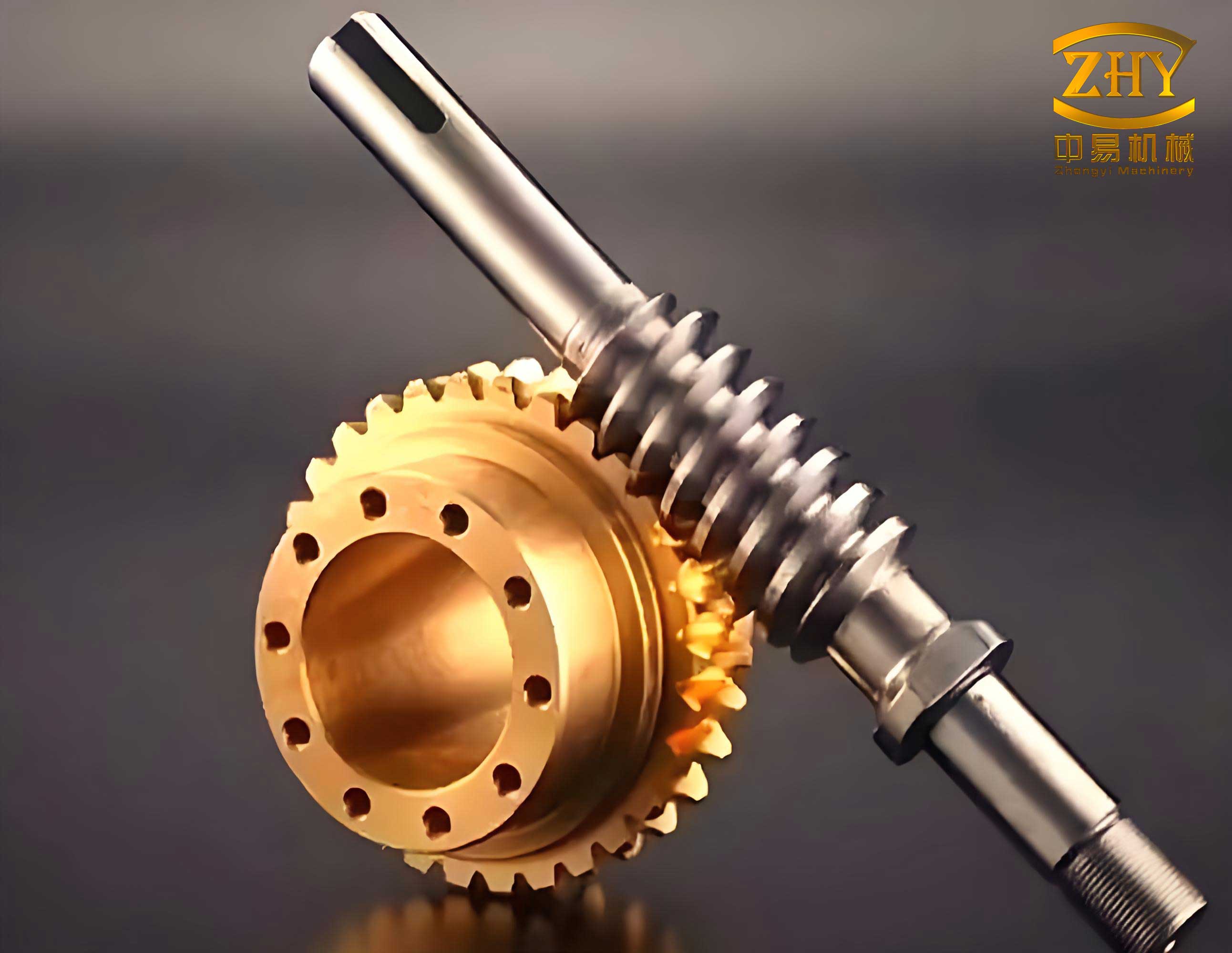
The material properties were assigned as follows: the worm was made of 20CrMnTi steel with an elastic modulus $E_1 = 199 \text{ GPa}$, Poisson’s ratio $\mu_1 = 0.27$, and density $7827 \text{ kg/m}^3$; the worm wheel was made of QSn6.5-0.1 bronze with $E_2 = 103 \text{ GPa}$, $\mu_2 = 0.3$, and density $8850 \text{ kg/m}^3$. These materials are common in screw gears for their balance of strength and wear resistance. Boundary conditions were applied to mimic real operating conditions: the worm wheel’s inner surface was fully constrained, while the worm was allowed to rotate only about its axis, with tangential forces applied to simulate torque. Loads ranging from 200 N·m to 2240 N·m were used to study the response of screw gears under different conditions.
The finite element analysis revealed intricate details about stress distribution in screw gears. For instance, under a torque of 1500 N·m, the contact stress on the first engaging tooth (tooth #1) showed a U-shaped pattern along the tooth length, with higher stresses at the ends and lower in the middle. This pattern aligns with empirical observations where pitting often occurs near the root and at the edges of screw gear teeth. To quantify load sharing among multiple teeth, I extracted data on torque distribution during meshing. The table below summarizes the percentage of total load carried by each tooth for different input torques in screw gears:
| Torque (N·m) | Tooth #1 (%) | Tooth #2 (%) | Tooth #3 (%) | Tooth #4 (%) |
|---|---|---|---|---|
| 200 | 72.3 | 14.7 | 8.5 | 4.5 |
| 1000 | 70.1 | 15.3 | 9.1 | 5.5 |
| 1500 | 66.5 | 17.4 | 10.7 | 5.4 |
| 2240 | 60.2 | 20.8 | 7.8 | 11.2 |
From this table, it is evident that the first tooth in screw gears bears the majority of the load, ranging from 60.2% to 72.3% depending on torque. As torque increases, the load share on the first tooth decreases slightly, but it remains dominant, highlighting the importance of designing screw gears with robust leading teeth to prevent premature failure. This load distribution behavior is critical for optimizing screw gear designs to ensure even wear and extended lifespan.
Next, I compared the results from analytical formulas and finite element simulations for both contact and bending stresses in screw gears. The analytical contact stress was calculated using the derived formula with parameters: $Z_E = 150 \text{ MPa}^{1/2}$ (typical for steel-bronze pairs), $Z_\rho = 0.95$ (from geometry), $T_2 = 7250 \text{ N·m}$, $K_A = 1.0$, and $a = 500 \text{ mm}$. Similarly, bending stress was computed using the approximate formula. The finite element results were obtained by averaging stress values over the critical regions. The comparison is presented in the following tables for different torque levels in screw gears:
| Torque $T_2$ (N·m) | Analytical Contact Stress $\sigma_H$ (MPa) | FEA Contact Stress (MPa) | Difference (%) |
|---|---|---|---|
| 7250 | 104.1 | 90 | 13.6 |
| 11400 | 130.5 | 114 | 12.4 |
| 15500 | 152.2 | 135 | 11.5 |
| Torque $T_2$ (N·m) | Analytical Bending Stress $\sigma_F$ (MPa) | FEA Bending Stress (MPa) | Difference (%) |
|---|---|---|---|
| 7250 | 9.4 | 8.1 | 13.8 |
| 11400 | 14.8 | 12.5 | 15.5 |
| 15500 | 20.2 | 17.3 | 14.4 |
The tables show that analytical methods yield stress values approximately 11.5% to 15.5% higher than finite element results for screw gears. This overestimation is due to simplifications in the analytical models, such as assuming uniform load distribution and ignoring local stress concentrations. In contrast, FEA captures the complex geometry and contact conditions of screw gears more accurately, providing a refined stress assessment. This validation confirms that finite element analysis is a reliable tool for strength evaluation of screw gears, though analytical formulas remain useful for initial design checks due to their simplicity.
To further explore the behavior of screw gears, I analyzed the influence of key parameters on stress levels. For example, the center distance $a$ and module $m$ significantly affect the strength of screw gears. Using the analytical formulas, I derived sensitivity equations to optimize these parameters. The contact stress $\sigma_H$ is inversely proportional to $a^{3/2}$, meaning that increasing the center distance reduces contact stress in screw gears. Similarly, bending stress $\sigma_F$ is inversely proportional to $m b_2$, so selecting larger modules or wider face widths can enhance bending resistance. These relationships are crucial for designing screw gears that meet specific load requirements while minimizing size and weight.
In addition to static strength, dynamic factors such as shock loads and thermal effects can impact screw gear performance. Screw gears often operate in environments with varying speeds and temperatures, which may alter material properties and lubrication conditions. Future studies could incorporate transient analysis or coupled thermal-structural simulations to assess these effects. For instance, using FEA, one could model the heat generation due to friction in screw gears and its influence on stress distribution. This would provide a more comprehensive strength analysis for screw gears in real-world applications.
Another aspect worth considering is the manufacturing tolerances and surface finishes of screw gears. Deviations from ideal geometry can lead to uneven load distribution and increased stresses. In my finite element model, I assumed perfect tooth profiles, but in practice, screw gears may have errors from machining or assembly. By introducing small perturbations in the FEA model, one could evaluate the sensitivity of screw gears to such imperfections. This knowledge can inform quality control measures and tolerance specifications for screw gear production.
Moreover, the lubrication regime plays a vital role in the strength of screw gears. Proper lubrication reduces friction and wear, thereby lowering contact stresses. The Hertzian formulas used in analytical methods assume dry contact, but in reality, screw gears are often lubricated. FEA can be extended to include fluid-structure interaction to model lubricant films and their effect on stress distribution. This advanced analysis would help optimize lubrication systems for screw gears, enhancing their durability and efficiency.
From a design perspective, the findings of this study emphasize the importance of using finite element analysis for accurate strength assessment of screw gears. While analytical methods provide a quick estimate, they tend to be conservative, potentially leading to over-designed screw gears that are heavier and more costly. By leveraging FEA, engineers can achieve lighter and more efficient screw gear designs without compromising safety. For example, the U-shaped stress distribution observed in FEA suggests that reinforcing the tooth ends or optimizing the profile could reduce peak stresses in screw gears.
To illustrate the application of these methods, consider a case study where screw gears are used in a conveyor system requiring high torque transmission. Using the parameters from this analysis, one could design a ZC1 screw gear set with a center distance of 500 mm and module of 20 mm. Based on FEA results, the maximum contact stress under 15500 N·m torque is 135 MPa, which is below the allowable stress for bronze, ensuring a long service life. Similarly, bending stress is within safe limits, preventing root fractures. This demonstrates how integrated analytical and numerical approaches can guide the reliable design of screw gears for industrial machinery.
In conclusion, the strength analysis of ZC1 circular cylindrical screw gears reveals that both analytical and finite element methods are valuable tools. Analytical formulas, derived from Hertzian theory and gear mechanics, offer simplicity and conservatism, making them suitable for preliminary design. However, finite element analysis provides a more accurate representation of stress states, capturing complex phenomena like load distribution and contact patterns in screw gears. The comparison shows that analytical results are about 11.5% to 15.5% higher than FEA results, validating FEA as a precise method for screw gear strength evaluation. Key insights include the dominant load-bearing role of the first tooth and the U-shaped stress distribution along the tooth length in screw gears. These findings can inform design improvements, such as optimizing tooth geometry and load-sharing mechanisms. As screw gears continue to be integral in power transmission systems, advancing their strength analysis through computational methods will enhance performance and reliability. Future work could explore dynamic loading, thermal effects, and manufacturing variances to further refine the design of screw gears for diverse engineering applications.
Throughout this article, the term “screw gears” has been emphasized to underscore the focus on this specific type of worm drive. By integrating formulas, tables, and simulation results, I have aimed to provide a thorough resource for engineers and researchers working with screw gears. The methods discussed here are not only applicable to ZC1 types but can be adapted to other screw gear configurations, contributing to the broader field of gear transmission technology. As I continue to investigate advanced manufacturing techniques, I believe that combining theoretical and computational approaches will drive innovation in screw gear design, leading to more efficient and durable mechanical systems.