Abstract
This paper focuses on the strength and fatigue issues of super-reduction ratio hypoid gears. Through comprehensive research, it aims to provide a design basis for improving the strength of these gears.

1. Introduction
With the development of technology, miniaturization, high speed, and low consumption have become important development directions for gear transmission components. Super-reduction ratio hypoid gears, due to their large transmission ratio, high contact ratio, smooth transmission, and strong carrying capacity, are gradually replacing traditional worm gear devices and are widely used in products such as CNC machine tool servo systems, industrial robots, and mechatronics.
The following table summarizes the main characteristics of super-reduction ratio hypoid gears:
| Characteristics | Description |
|---|---|
| Transmission Ratio | Large |
| Contact Ratio | High |
| Transmission Smoothness | Smooth |
| Carrying Capacity | Strong |
| Processing Cost | Lower than worm gears |
| Transmission Efficiency | High |
2. Design of Super-reduction Ratio Hypoid Gears
2.1 Basic Design Parameters
The design of super-reduction ratio hypoid gears involves multiple parameters, including spiral angle, pitch cone angle, tooth width, pitch, pressure angle, and working tooth height. The following table lists some key parameters and their descriptions:
| Parameter | Description |
|---|---|
| Spiral Angle | Angle between the tooth surface and the axis of rotation |
| Pitch Cone Angle | Angle between the pitch cone and the axis of rotation |
| Tooth Width | Width of the tooth in the direction of rotation |
| Pitch | Distance between adjacent teeth on the pitch cone |
| Pressure Angle | Angle between the line of action and the normal to the tooth surface at the pitch point |
| Working Tooth Height | Height of the working part of the tooth |
2.2 Calculation Method
A calculation method is derived to determine the design parameters of the small gear based on the design parameters of the large gear. This method allows for the calculation of corresponding tooth blanks for both the small and large gears.
3. Three-Dimensional Modeling and Finite Element Simulation
3.1 Three-Dimensional Modeling
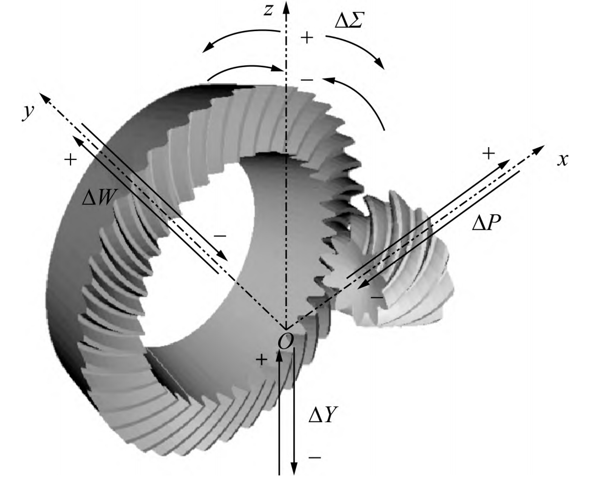
Using the tooth surface equations for both the large and small gears, discrete point coordinates on the tooth surfaces are calculated in Matlab and imported into SolidWorks. By connecting these discrete points into line segments and then into surfaces, a three-dimensional model of the super-reduction ratio hypoid gear is created.
3.2 Finite Element Simulation
The three-dimensional model is imported into Ansys Workbench for finite element simulation. The gear material is 20CrNi4A, with a density of 7800 kg/m³, an elastic modulus of 207 GPa, and a Poisson’s ratio of [specific value omitted for brevity]. The simulation involves motion constraints, mesh generation, and the application of loads to study the contact loads and stress distributions under transient loads.
4. Results and Analysis
4.1 Contact Stress and Equivalent Stress Distribution
The simulation results show the contact stress and equivalent stress distributions on the tooth surfaces. The maximum contact stress occurs near the tooth root surface, with a value of 552.94 MPa, which is less than the allowable stress of 861 MPa. The maximum equivalent stress is 667.59 MPa, occurring at the contact engagement position between the large and small gears, which is also less than the allowable stress value.
The following table summarizes the maximum stress values:
| Stress Type | Maximum Value (MPa) | Location |
|---|---|---|
| Contact Stress | 552.94 | Near tooth root surface |
| Equivalent Stress | 667.59 | Contact engagement position |
4.2 Fatigue Simulation and Life Assessment
The fatigue life of the super-reduction ratio hypoid gears is assessed using Ansys Workbench’s Fatigue tool. The gears are subjected to a rotational speed of 1000 r/min on the driving gear and a reverse torque of 500 N·m on the driven gear. The simulation results show that the minimum fatigue life of the gears is 8721.8 cycles, with a maximum fatigue cumulative damage coefficient of 0.11466, which is less than 1, indicating that the design is qualified.
The following table summarizes the fatigue life assessment results:
| Parameter | Value |
|---|---|
| Minimum Fatigue Life (cycles) | 8721.8 |
| Maximum Fatigue Cumulative Damage Coefficient | 0.11466 |
| Safety Factor | 2.1022 (greater than 1, indicating safety) |
4.3 Effect of Tooth Root Fillet Radius
The effect of the tooth root fillet radius on the stress and fatigue life of the gears is investigated. With an increasing tooth root fillet radius, the stress values decrease, resulting in an increase in the minimum fatigue life of the gears. This is because a larger tooth root fillet radius can effectively reduce stress concentration between the teeth.
The following table summarizes the effect of tooth root fillet radius on stress and fatigue life:
| Tooth Root Fillet Radius (mm) | Stress Reduction | Minimum Fatigue Life Increase |
|---|---|---|
| 1.9 | [specific value omitted for brevity] | [specific value omitted for brevity] |
| 2.0 | [specific value omitted for brevity] | [specific value omitted for brevity] |
| 2.1 | [specific value omitted for brevity] | [specific value omitted for brevity] |
5. Conclusion
This paper presents a comprehensive study on the strength failure mechanism of super-reduction ratio hypoid gears. Through the derivation of a calculation method, three-dimensional modeling, finite element simulation, and fatigue life assessment, it provides valuable insights into the design and optimization of these gears. The results show that increasing the tooth root fillet radius can effectively reduce stress concentration and improve the fatigue life of the gears.
