
As shown in the figure, the structure diagram of the final forging die for the half shaft gear is given. Since the final forging temperature is lower than the pre forging temperature, the tooth die is designed in the lower die, so the problem of too high temperature rise of the tooth die will not occur. At the same time, it is convenient for the forgings to align the final forging with the tooth shape. When the final forging is placed, the deformation of the half shaft gear blank is small, and the stroke of the sliding block is far less than the lock guide length. Therefore, the lock guide is adopted for the die. Because the friction of the half shaft cavity to the workpiece is large, the, The half shaft gear workpiece is stuck in the half shaft concave die. In order to facilitate the smooth demoulding of the workpiece, the upper formwork is designed with an elastic jacking device.
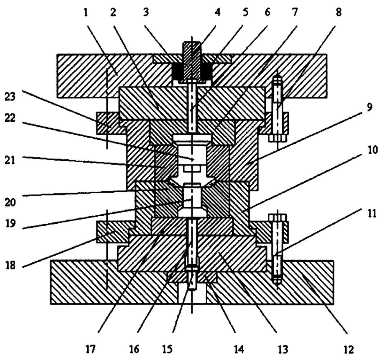
The upper base plate 2 and the lower base plate 13 are respectively fixed on the upper and lower formworks with screws. In order to make the figure clear, the screws connecting the upper and lower base plates and the upper and lower formworks are not drawn as shown in the figure. The tooth mold 20 and the tooth mold sleeve 10 are prestressed, and the screw 11 uses the lower pressing ring 18 to fix the tooth mold sleeve on the lower template. The half shaft die 21 and the half shaft die sleeve 9 are prestressed, and the screw 8 uses the upper pressing ring 23 to fix the half shaft die sleeve on the upper formwork.
The forging of the half shaft gear starts, the upper punch 22 is at the lower limit position under the action of the spring 5, the upper die goes down, the latch of the gear die sleeve 10 and the half shaft female die sleeve 9 is first introduced into the upper die to continue to go down, the upper punch 22 contacts with the blank, the spring 5 is compressed, the half shaft gear blank begins to be forged, after the forging, the upper die goes up, the forging deformation force is eliminated, and the spring tension makes the forging separate from the half shaft female die, The forging is ejected by the lower ejector of the friction press.