
The structure of the gear turning cutter is similar to that of the helical cylindrical gear. The three-dimensional shape of the gear turning cutter can be obtained by adding the front angle and back angle of the cutter to the helical cylindrical gear.
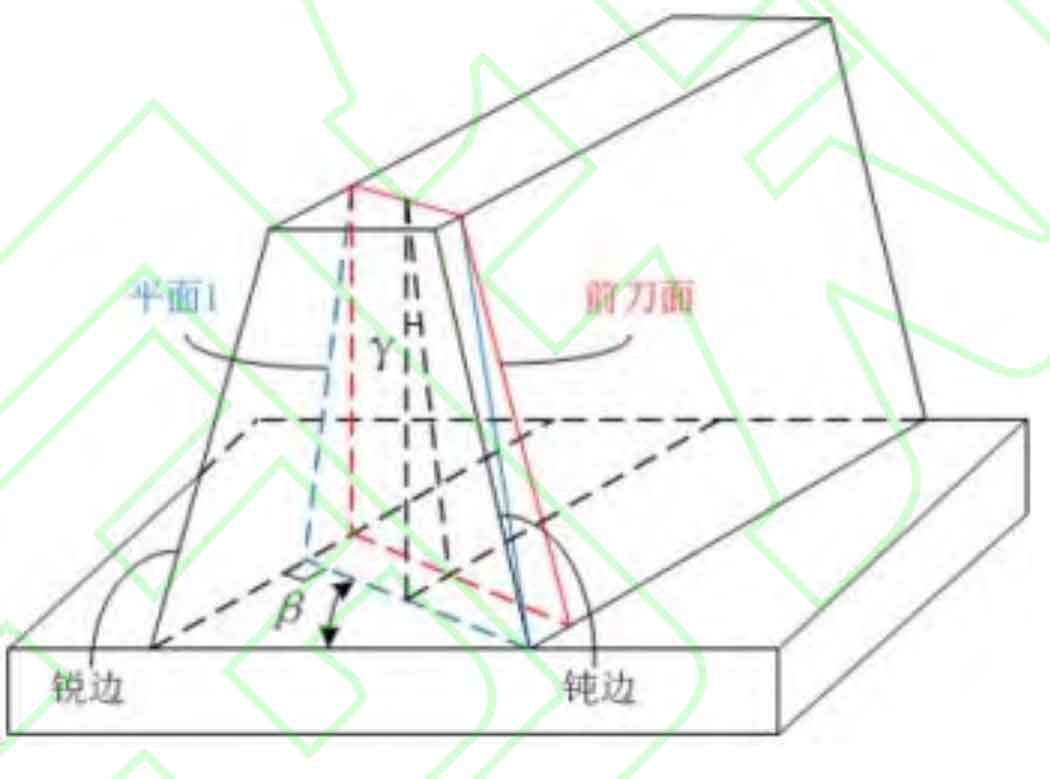
The rake face is the most important factor in the cutting process. Because it is in direct contact with the chip layer of the workpiece, the chip deforms and breaks on it, which directly affects the cutting quality of the workpiece surface. For ease of illustration, the oblique rack is used as an example to describe the formation process of the rake face of the gear turning cutter, as shown in Figure 1. The gear turning cutter is similar to a helical gear. If the end plane is directly selected as the rake face, there will be two side edges, one of which has a negative machining rake angle. We call this side edge a blunt edge. In order to avoid the above situation, the rake face needs to produce an included angle 𝛽 with the end face, and 𝛽 is exactly equal to the spiral angle of the gear turning tool, so as to form plane 1. At the same time, in order to ensure that the top edge has a positive rake angle, the rake face needs to form an angle 𝛾 with plane 1. At the same time, both sides of the rake face are set in a bowl shape to increase the machining rake angle of the blades on both sides, so that the rake faces on both sides have different values of 𝛽, which are 𝛽 1 and 𝛽 2 respectively, so as to obtain the final rake face. Designed 𝛾 = 3 °, 𝛽 = 23 °, 𝛽 1 = 5 °, 𝛽 2 = 70 °.
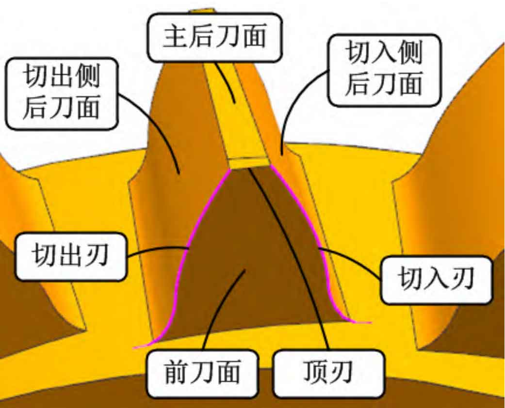
The flank of the gear turning cutter is divided into the main flank, the flank of the cutting side and the flank of the cutting out side (since the two sides of the gear turning cutter do not cut in and cut out the workpiece at the same time in the actual machining process, it is defined that one side of the blade that cuts into the workpiece first is the cutting in edge and the other side is the cutting out edge). In order to ensure that the flank of the cutter does not contact with the workpiece during the gear turning machining process, the main flank is designed as a conical surface, The flank flank is designed into helical surfaces with different helical angles. Figure 2 shows the structural diagram of gear turning cutter.