
(1) Outer diameter of gear hob
The outer diameter of gear hob not only affects the stability of cutting, but also affects the rationality of the main parameters such as the diameter and circumference of gear hob and the manufacturing technology of gear hob.
The principle of selecting the outer diameter of gear hob is that when the precision of the processed gear is high or the number of teeth is large, the outer diameter of gear hob shall be larger as far as possible. Generally, the outer diameter of gear hob can be reduced as far as possible under the condition of sufficient stiffness.
(2) Length of gear hob
The minimum length of gear hob must meet the following two conditions:
A gear hob can envelope the complete tooth profile of the processed gear;
B. the load on the edge of gear hob shall not be too heavy.
(3) Back angle and back clearance of gear hob
The back angle of gear hob is obtained by radial back measurement. Relationship between back angle and shovel back:
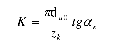
Where e α Shall be greater than or equal to 3 °. α E is actually the projection of the back angle of the top edge of the gear hob in the end face. The true back angle of hob shall be measured in the direction of helix. However, because the spiral rise angle of gear hob is generally small, and the rear angle value allows relatively large tolerance, it is completely possible that the rear angle in the helix direction is equal to the rear angle of the end section.
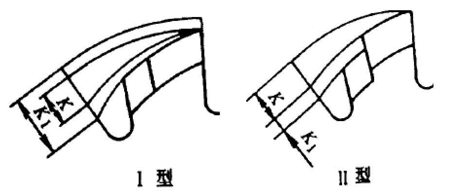
The hob to be ground must have a double shovel back. The hob blade with double shovel back has two different forms:
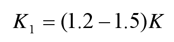
① Type I, as shown in Figure (type I). Shovel back 1K can be taken:
② Type II, as shown in Figure.
(4) Indexing diameter of gear hob
The indexing diameter of gear hob is determined by the following equation:
Spiral rise angle of indexing circle of gear hob:
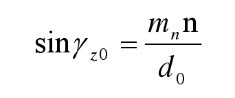
Where n — number of hobs.
(5) Pitch of gear hob
① Normal pitch of gear hob:
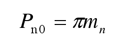
Where nm – normal modulus of the gear to be machined, unit: mm.
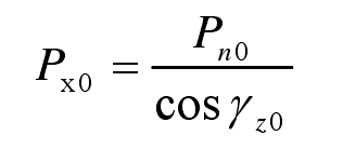
② Axial pitch of gear hob:
(6) Tooth thickness of gear hob
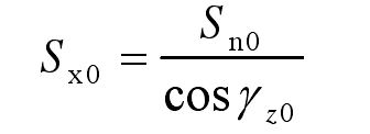
Where sn0 – normal spiral tooth thickness of the gear to be machined on the indexing circle, unit: mm.
(7) Tooth top height and tooth root height of gear hob
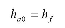
① Addendum height of gear hob
② Tooth root height of gear hob
The tooth root height h F0 of the gear hob is equal to the sum of the tooth top height h a and the top clearance C of the processed gear, that is:
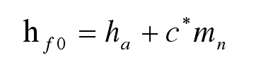
Where c * — top clearance coefficient of the gear to be cut.
(8) Chip holding groove of gear hob
The chip holding groove of gear hob is divided into straight groove and spiral groove. In order to improve the manufacturing and grinding accuracy of hobs, gear hobs are generally made into straight grooves, which are easy to check.
When the spiral rising angle of gear hob γ When Z0 ≤ 50 °, the chip holding groove of the hob is made into a straight groove γ When Z0 ≥ 50 °, the chip holding groove is made into a spiral groove.
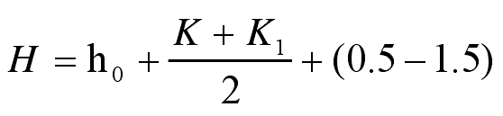
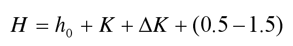
Depth of chip holding groove H
Type I tooth back:
Type II tooth back:
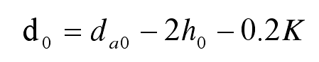
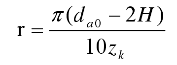
Calculation of radius r of chip holding groove bottom:
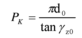
Calculation formula of lead KP of spiral groove:
Groove angle θ :
When ≤ 9nm, take θ °= 25 ;
When ≥ 9nm, take θ °= 22 。