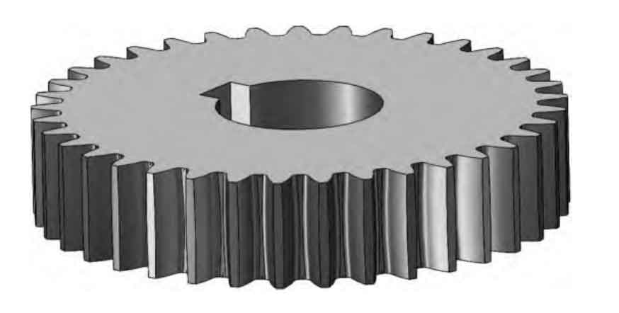
In reliability analysis of cylindrical gear systems, design parameters and boundary conditions often involve mixed uncertainties, including both random and interval variables. Traditional probabilistic reliability methods fail to address such hybrid scenarios due to incompatible measure spaces. This study proposes a second-order reliability method (SORM) incorporating polar coordinate transformations to resolve this challenge.
1. Hybrid Uncertainty Quantification Framework
For cylindrical gear systems, let the limit state function be expressed as \( G(\mathbf{X}, \mathbf{Y}) \), where:
- \(\mathbf{X} = (X_1, X_2, \ldots, X_n)\): Random variables (e.g., material properties)
- \(\mathbf{Y} = (Y_1, Y_2, \ldots, Y_m)\): Interval variables (e.g., load ranges)
The failure probability \( P_f \) is formulated as:
$$ P_f = \text{Pr}\left[G(\mathbf{X}, \mathbf{Y}) \leq 0\right] = \int_{G(\mathbf{x},\mathbf{y}) \leq 0} f_{\mathbf{X}}(\mathbf{x}) \, d\mathbf{x} $$
| Variable Type | Examples | Distribution/Interval |
|---|---|---|
| Random | Tooth width, hardness | Normal distribution |
| Interval | Operational torque, RPM | [Lower, Upper] bounds |
2. Polar Coordinate Transformation
Key steps for cylindrical gear reliability analysis:
2.1 Standard Normal Space Conversion
Transform variables to independent standard normal space:
$$ \mathbf{U} = T_{\text{random}}(\mathbf{X}), \quad \mathbf{\Delta} = T_{\text{interval}}(\mathbf{Y}) $$
2.2 Second-Order Approximation
Expand limit state function at Most Probable Point (MPP):
$$ G(\mathbf{\omega}) \approx G(\mathbf{\omega}^*) + \nabla G(\mathbf{\omega}^*)(\mathbf{\omega} – \mathbf{\omega}^*) + \frac{1}{2}(\mathbf{\omega} – \mathbf{\omega}^*)^T \mathbf{H}(\mathbf{\omega}^*)(\mathbf{\omega} – \mathbf{\omega}^*) $$
where \(\mathbf{\omega} = (\mathbf{U}, \mathbf{\Delta})\) represents combined variables.

2.3 Polar Coordinate Mapping
Define polar coordinates \((v_1, v_2)\):
$$ v_1 = \|\mathbf{\omega}\|_2 = \sqrt{\sum_{i=1}^n U_i^2 + \sum_{j=1}^m \Delta_j^2} $$
$$ v_2 = \cos\theta = \frac{\mathbf{\omega} \cdot \mathbf{\alpha}}{\|\mathbf{\omega}\|\|\mathbf{\alpha}\|} $$
3. Probabilistic Modeling
The joint probability density function becomes:
$$ \phi(v_1, v_2) = \phi_1(v_1) \cdot \phi_2(v_2) $$
| Variable | Distribution | Expression |
|---|---|---|
| \(v_1\) | Generalized Chi-square | \(\phi_1(v_1) \propto v_1^{n+m-1} e^{-v_1^2/2}\) |
| \(v_2\) | Angular Projection | \(\phi_2(v_2) \propto \sin^{n+m-2}(\arccos v_2)\) |
4. Case Study: Cylindrical Gear Contact Fatigue
Analyze contact stress reliability for industrial cylindrical gears:
4.1 System Parameters
| Parameter | Value | Uncertainty Type |
|---|---|---|
| Module (mm) | 8.654 | Deterministic |
| Tooth Width (mm) | \(\mathcal{N}(52.521, 0.03^2)\) | Random |
| Torque (Nm) | [3580, 3660] | Interval |
4.2 Limit State Function
Contact stress formulation for cylindrical gears:
$$ \sigma_H = Z_H Z_E Z_\epsilon Z_\beta Z_K \sqrt{\frac{K_A K_V K_{H\beta} K_{H\alpha} F_{tm}}{d_{m1} b_{eH}} \cdot \frac{u^2 + 1}{u} $$
Where \( F_{tm} = \frac{2000T}{d_{m1}} \) represents tangential force.
4.3 Reliability Results
| Method | Lower Bound | Upper Bound | Computation Time (s) |
|---|---|---|---|
| Monte Carlo | 0.0031 | 0.5776 | 4.2 |
| Classical SORM | 0.0051 | 0.5718 | 3.2 |
| Proposed Method | 0.1874 | 0.3827 | 2.3 |
5. Conclusion
The proposed SORM-based hybrid reliability method demonstrates:
- 65.99% reduction in failure probability interval width compared to conventional methods
- 35% improvement in computational efficiency
- Effective handling of cylindrical gear systems with mixed uncertainties
This methodology provides crucial insights for reliability-driven design of cylindrical gears in power transmission systems, particularly when dealing with incomplete statistical information.
