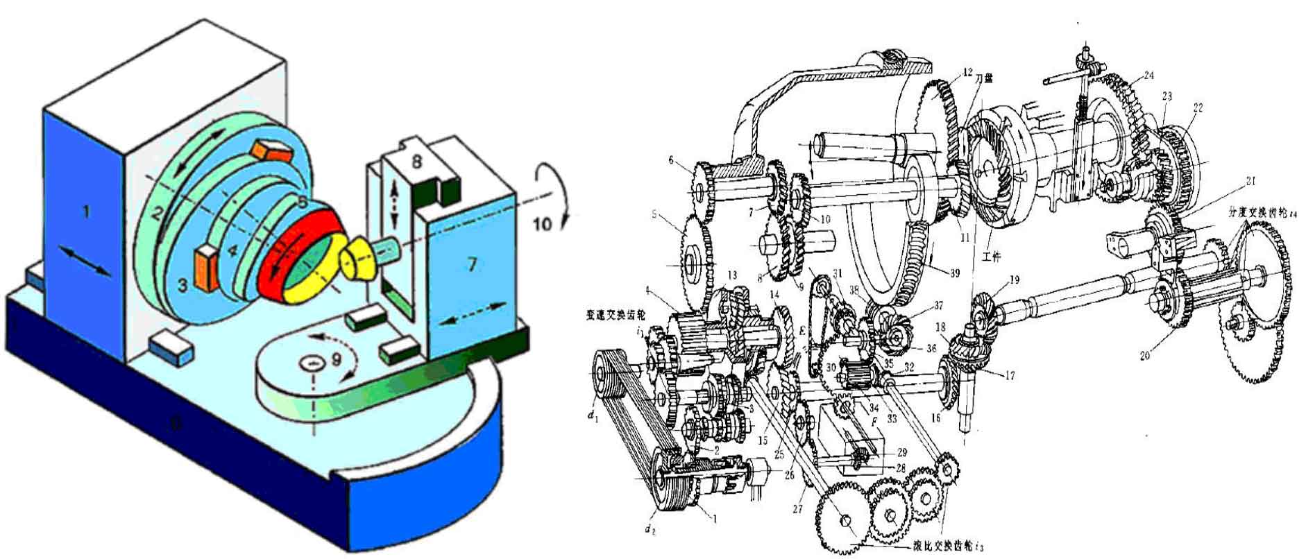
The earlier gear cutting of spiral bevel gear was carried out on mechanical gear milling machine. The mechanical gear milling machine adopts the shaking table structure, as shown in the figure. The shaking table (2) is equipped with an eccentric mechanism (3), a knife rotating body (4) and a knife tilting body (5). During gear cutting, the cutter head is installed on the cutter tilt body, and the cutter tilt body and cutter rotation body can adjust the angle between the cutter head axis and the shaking table axis and the tilt direction of the cutter head axis; The eccentric mechanism can adjust the distance from the center of the cutter head to the center of the shaking table. The processed spiral bevel gear is installed on the workpiece spindle (10), and the axis direction, axial position and height of the workpiece spindle (installation root cone angle, horizontal wheel position and vertical wheel position of the machine tool) are adjusted by the lead screw guide rail or chain transmission mechanism.
The shaking table drives the cutter head to rotate to form a virtual forming wheel, and the spiral bevel gear meshes with the virtual forming wheel to form a tooth surface. The mechanical structure of mechanical gear milling machine is complex, and the corresponding mechanism needs to be adjusted manually for each cutting adjustment parameter. Moreover, since the machine tool has only one driving motor, its tooth splitting, generating and cutting movements are transferred through the complex spiral bevel gear transmission chain. If these movements need to be changed, they should be realized by replacing the corresponding change gear. The adjustment cycle of the machine tool is long, so the processing efficiency is low. On the other hand, because there are many mechanical adjustment links, each link will bring in adjustment errors, which will have a great impact on the tooth profile; The manufacturing error of the spiral bevel gear itself will also have a direct impact on the tooth division of the spiral bevel gear, which makes it difficult to control the tooth profile error of the processed spiral bevel gear and improve the pitch accuracy.
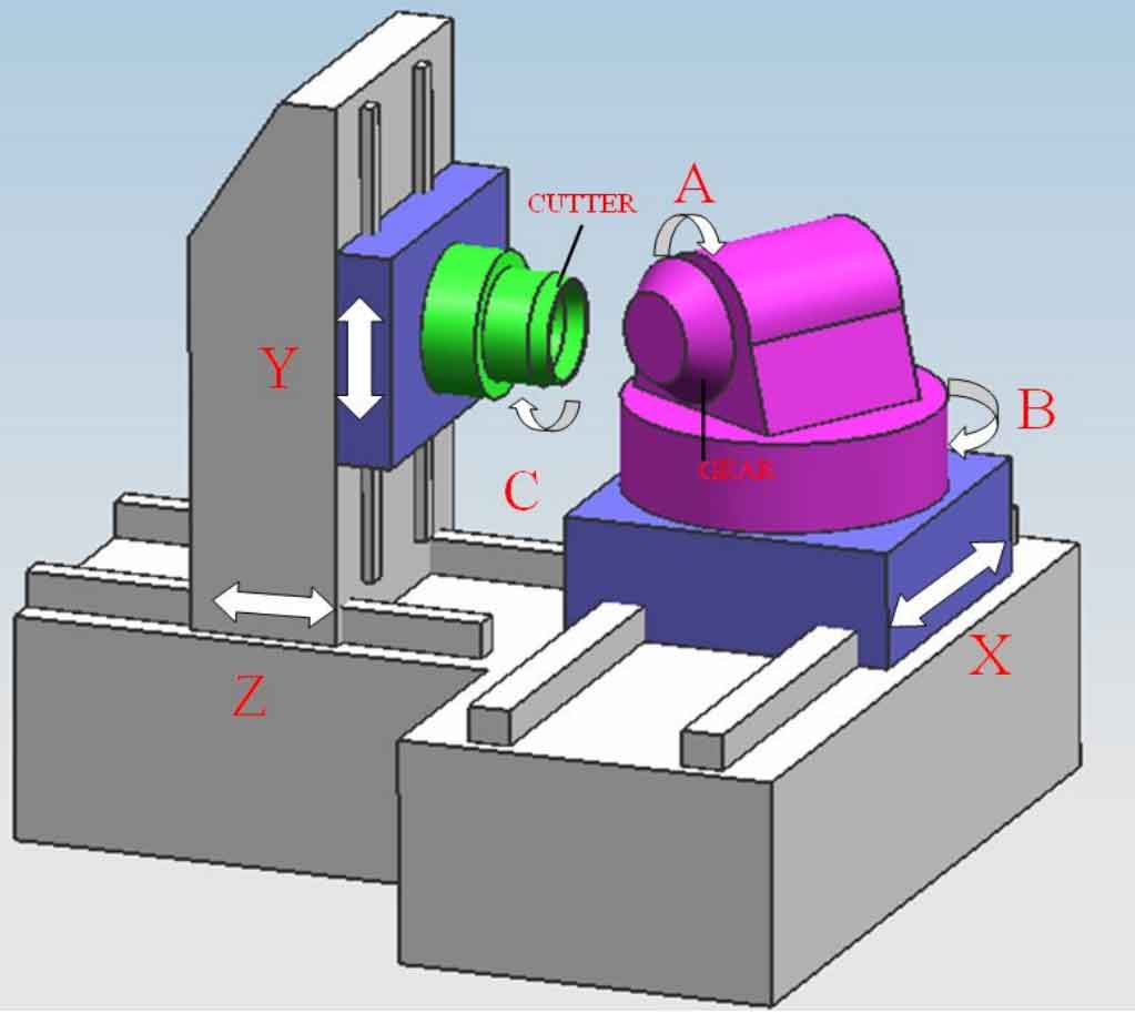
In order to improve the machining accuracy of spiral bevel gears, it is necessary to minimize mechanical adjustment links and manual intervention. With the development of numerical control technology, the full digital control of gear milling machine is the development direction in the future. As shown in the figure, it is the machine tool structure schematic diagram of the full CNC spiral bevel gear milling machine. For the full CNC gear milling machine, the rotation of the shaping wheel in the machining process is not realized by the rotation of the shaking table, but by the circular interpolation movement of the cutter head driven by two linear coordinate axes. The machine tool has six coordinate axes. The cutter head is located on the left side of the machine tool. It moves up and down and back and forth driven by Y-axis and z-axis. The rotation of the cutter head itself is c-axis; The spiral bevel gear is located on the right side of the machine tool. It moves longitudinally driven by the x-axis, swings around the y-axis driven by the b-axis, and rotates around its own axis driven by the a-axis. 10. Y linkage simulates the rotation of the shaking table, Z axis controls the cutting depth, and b axis adjusts the root cone angle of spiral bevel gear. The relative position and relative motion adjustment of spiral bevel gear and tool can be realized by the positioning motion and linkage motion of these six coordinate axes, which greatly reduces the transmission link and manual intervention. Therefore, high relative positioning and relative motion accuracy of spiral bevel gear and tool can be obtained, which can greatly improve the machining accuracy of spiral bevel gear.
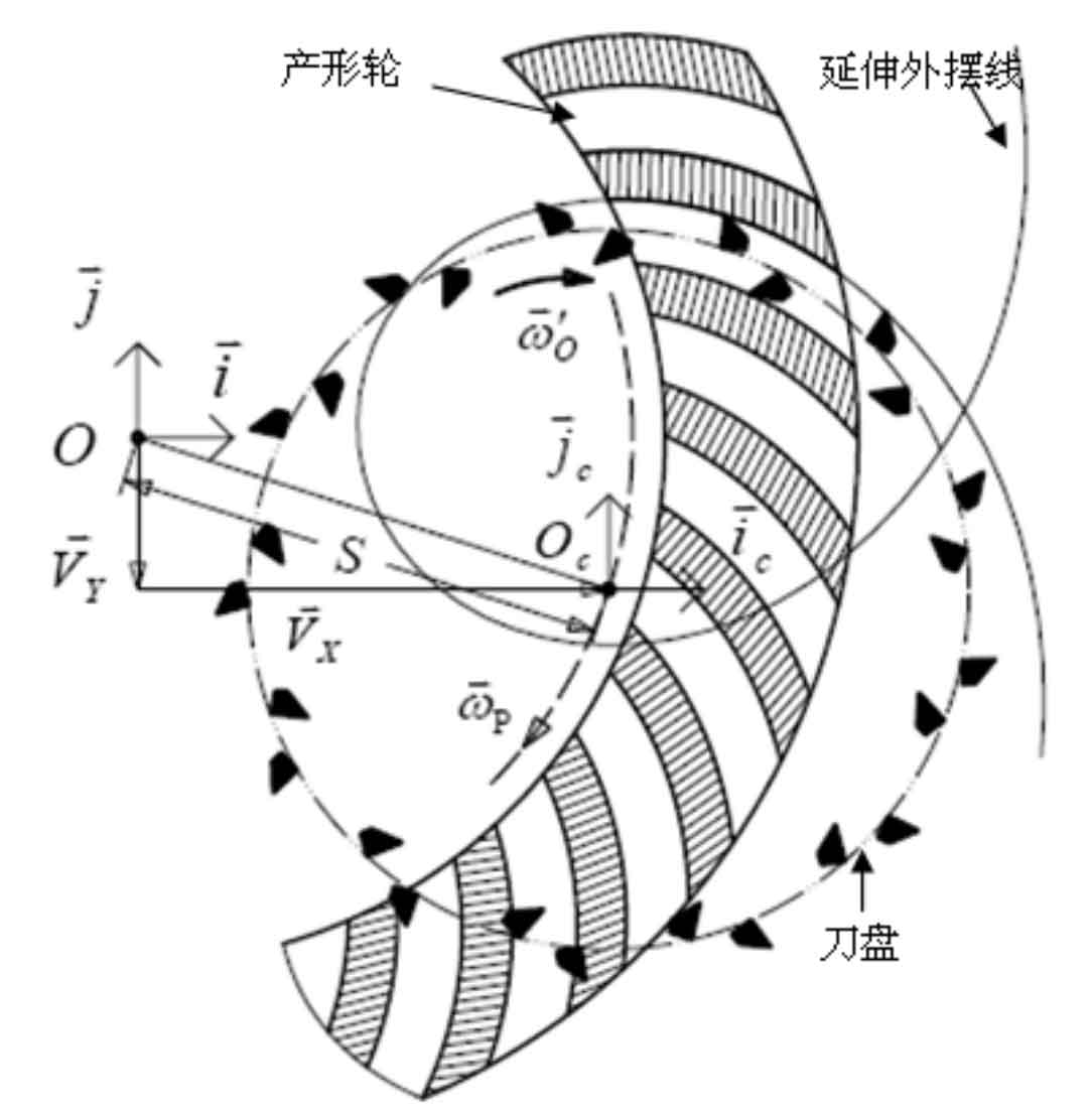
From the above analysis, it can be seen that the machine structure of all CNC machine tools has changed greatly compared with mechanical machine tools, and the most obvious change is that the shaking table has been cancelled. Thus, the rotation motion of the production wheel represented by it is replaced by the circular arc interpolation motion of the linear coordinate axis, which can be regarded as a virtual shaking table rotation ω P 。