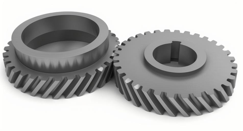
Helical gears play a critical role in power transmission systems due to their smooth engagement and high load-carrying capacity. This paper investigates the adhesion wear characteristics of helical gear pairs under dry friction conditions through quasi-static numerical modeling and parametric analysis.
1. Meshing Characteristics of Helical Gears
The contact line length variation during meshing is determined by the relationship between transverse contact ratio (εα) and overlap ratio (εβ):
$$l(1,t) =
\begin{cases}
\frac{P_{bt}}{\sin\beta_b}\left(\frac{t}{T_m}\right) & 0 \leq t \leq \epsilon_\alpha T_m \\
\frac{P_{bt}}{\sin\beta_b}\epsilon_\alpha & \epsilon_\alpha T_m < t \leq \epsilon_\beta T_m \\
\frac{P_{bt}}{\sin\beta_b}\left(\epsilon_\gamma – \frac{t}{T_m}\right) & \epsilon_\beta T_m < t \leq \epsilon_\gamma T_m \\
0 & \text{otherwise}
\end{cases}$$
Key meshing parameters include:
| Parameter | Expression |
|---|---|
| Normal Load | $$F_n = \frac{2T_1}{d_1\cos\alpha_n\cos\beta_b$$ |
| Contact Pressure | $$p(i,j) = \frac{4F(1,t)}{3\pi bl(1,t)}$$ |
| Sliding Velocity | $$u_s = |\omega_1 R_1 – \omega_2 R_2|\cos\beta_b$$ |
2. Adhesive Wear Modeling
The modified Archard wear model for helical gears considers both sliding distance and contact pressure:
$$h_{dry}^{1,2}(i,j) = k \cdot p(i,j) \cdot S_{1,2}(i,j)$$
Where the sliding distance is calculated as:
$$S_{1,2}(i,j) = \frac{2b|u_1 – u_2|}{u_{1,2}}$$
| Parameter | Value |
|---|---|
| Module (mm) | 3 |
| Pressure Angle | 20° |
| Helix Angle | 15° |
| Wear Coefficient (K) | 1×10-16 |
3. Wear Distribution Characteristics
The numerical analysis reveals distinct wear patterns:
$$h_z^{1,2}(i,j) = \sum_{n=1}^N h_{dry}^{1,2}(i,j)$$
Key findings include:
- Maximum wear depth occurs at the pinion root (1.88×10⁻⁴ mm)
- Wear depth decreases by 63% at pitch point compared to root
- Pinion wear exceeds gear wear by 22-35% across the profile
4. Parametric Sensitivity Analysis
The effects of operational parameters on wear depth follow:
$$ \frac{\partial h_z}{\partial T} = 4.7\times10^{-7}\ \text{mm/Nm} $$
$$ \frac{\partial h_z}{\partial B} = -1.2\times10^{-6}\ \text{mm/mm} $$
| Parameter | 20% Increase Effect |
|---|---|
| Torque (200→240 Nm) | +18.7% wear depth |
| Helix Angle (15→18°) | -6.3% wear depth |
| Face Width (50→60 mm) | -15.4% wear depth |
5. Wear Mitigation Strategies
For helical gear systems operating under dry friction:
- Optimize helix angle between 20-25° for minimum wear
- Maintain face width-to-module ratio > 16:1
- Limit torque fluctuations to ±15% of rated value
This systematic investigation provides critical insights into helical gear wear mechanisms and establishes a foundation for predictive maintenance strategies in heavy-duty transmission systems.
