
Non-circular gears enable unique nonlinear motion transmission capabilities critical for automotive, robotics, and industrial machinery applications. While design methodologies for these components mature, manufacturing constraints—particularly gear hobbing stability—remain challenging. The non-uniform pitch curve curvature induces significant cutting force fluctuations during gear hobbing, causing vibration, tool wear, and dimensional inaccuracies. We establish a predictive framework linking undeformed chip geometry to cutting forces and propose mitigation strategies validated through kinematic modeling and experimental verification.
Hobbing Kinematics for Non-Circular Gears
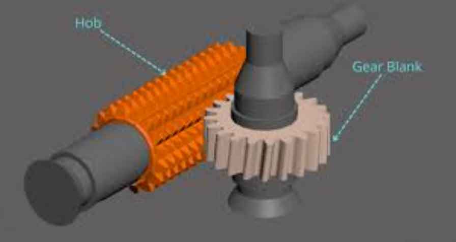
The hob-non-circular gear interaction projects as an equivalent rack-pitch curve pure-rolling motion. The fundamental linkage model coordinates four axes (B: hob rotation, C: gear rotation, X: radial feed, Z: axial feed):
$$
\begin{cases}
\omega_C = \frac{\sqrt{r^2 + (dr/d\phi)^2}}{r^2} \left( \frac{K_C \omega_B T m_n}{2 \cos \beta} + K_Z v_Z \tan \beta \right) \\
v_X = \frac{dr/d\phi}{r} \left( \frac{\omega_B T m_n}{2 \cos \beta} + K_Z v_Z \tan \beta \right)
\end{cases}
$$
where \(m_n\) = normal module, \(\beta\) = helix angle, \(T\) = hob threads, \(r\) = pitch curve radius, \(\phi\) = polar angle, and \(K_C\), \(K_Z\) = directional coefficients. Without hob shifting, the arc-length increment varies with curvature, causing force oscillations.
Undeformed Chip Geometry and Force Correlation
Cutting force magnitude correlates directly with undeformed chip volume per intermittent cutting event. We simulate chip formation via Boolean subtraction of the hob tooth swept volume from the gear blank. For cylindrical gears, volume periodicity aligns with measured force trends:
$$
F_c = S \cdot K_s, \quad K_s = K_c / h^u
$$
where \(F_c\) = cutting force, \(S\) = chip cross-section area, \(K_s\) = specific cutting force, \(h\) = chip thickness, and \(K_c\), \(u\) = material constants. Chip thickness variation contributes minimally to force deviations compared to cross-sectional area changes.
| Parameter | Value |
|---|---|
| Gear teeth | 30 |
| Normal module (mm) | 4 |
| Helix angle (°) | 15 |
| Pitch curve | Eccentricity 0.3 ellipse |
| Hob diameter (mm) | 100 |
| Hob grooves | 8 |
| Axial feed (mm/rev) | 2 |
Force Fluctuation Characteristics
Oval gear simulations reveal 19.3× chip volume variation under conventional gear hobbing. Force peaks occur at maximum pitch-curvature radius locations (minor axis) due to prolonged hob engagement:
$$
SY = r \cos \mu = \frac{r \cdot (dr/d\phi)}{\sqrt{r^2 + (dr/d\phi)^2}}
$$
Peak volumes at positions 60 and 180 (minor axis) correlate with experimental observations of machine vibration and audible chatter during minor-axis gear hobbing.
Constant Arc-Length Increment Model
To suppress fluctuations, we introduce hob-shifting axis (Y) compensation maintaining uniform projection rolling:
$$
\begin{cases}
\omega_C = \frac{\sqrt{r^2 + (dr/d\phi)^2}}{r^2} \left( \frac{K_C \omega_B T m_n}{2 \cos \beta} + K_Y v_Z \tan \beta + v_Y \frac{\cos \lambda}{\cos \beta} \right) \\
v_X = \frac{dr/d\phi}{r} \left( \frac{\omega_B T m_n}{2 \cos \beta} + K_Y v_Z \tan \beta + v_Y \frac{\cos \lambda}{\cos \beta} \right) \\
v_Y = v_Y(\phi) \frac{\cos \beta}{\cos \lambda}
\end{cases}
$$
where \(\lambda\) = hob installation angle. This reduces volume fluctuation to 6.2× and shifts peaks symmetrically around the minor axis. Experimental validation confirms eliminated vibration at 200 rpm hob speed.
Radial Depth of Cut Influence
Stepwise radial infeed further controls peak forces. Chip volume scales linearly with depth without altering fluctuation patterns:
| Depth of Cut (% of full) | Max Volume (mm³) | Min Volume (mm³) | Ratio |
|---|---|---|---|
| 25% | 37.6 | 7.1 | 5.3 |
| 50% | 75.3 | 14.2 | 5.3 |
| 75% | 112.9 | 21.3 | 5.3 |
| 100% | 150.5 | 28.4 | 5.3 |
Shallow multi-pass strategies lower absolute force magnitudes while maintaining process stability during gear hobbing of high-eccentricity profiles.
Conclusions
1. Undeformed chip volume predicts cutting force peaks during non-circular gear hobbing, with maxima occurring at maximum pitch-curvature radii under conventional kinematics.
2. Constant arc-length increment gear hobbing via active hob shifting reduces force fluctuations by 67.9% and redistributes peaks symmetrically around critical regions.
3. Radial depth adjustments proportionally scale cutting forces without altering fluctuation ratios, enabling optimized multi-pass strategies.
4. Integrated suppression techniques enhance process stability for complex non-circular gears, expanding their applicability in precision motion systems.