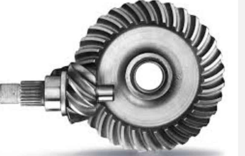
This paper investigates the fatigue failure characteristics and stress distribution patterns of hypoid gears under ultra-high reduction ratios through systematic parameter optimization and finite element analysis. A novel computational methodology for determining pinion design parameters based on gear blank geometry is proposed, enabling precise modeling and simulation of hypoid gear systems.
1. Geometric Parameter Design
The fundamental geometric parameters of hypoid gears are derived from spatial coordinate relationships and meshing kinematics. The pitch cone geometry satisfies the following relationships:
$$ \tan \delta’_2 = \frac{z_2 \sin \Sigma}{1.2(z_1 + z_2 \cos \Sigma)} $$
$$ r_2 = \frac{1}{2}(d_{e2} – b_2 \sin \delta’_2) $$
$$ \sin \varepsilon’_0 = \frac{E \sin \delta’_2}{r_2} $$
Key design parameters are optimized through iterative calculations:
| Parameter | Pinion | Gear |
|---|---|---|
| Number of Teeth | 2 | 60 |
| Module (mm) | 7.806 | 47.80 |
| Face Width (mm) | 88.19 | 238.86 |
| Pressure Angle (°) | 20 | |

2. Tooth Surface Modeling
The tooth surface coordinates are derived through spatial coordinate transformation matrices:
$$ \mathbf{r}_{01}^{(a)} = \begin{bmatrix}
(-r_{c1} \pm s_1 \sin \alpha_{01}) \sin \theta_1 \\
(-r_{c1} \pm s_1 \sin \alpha_{01}) \cos \theta_1 \\
-s_1 \cos \alpha_{01}
\end{bmatrix} $$
$$ \mathbf{n}_{01}^{(a)} = \begin{bmatrix}
-\cos \alpha_{01} \sin \theta_1 \\
-\cos \alpha_{01} \cos \theta_1 \\
\mp \sin \alpha_{01}
\end{bmatrix} $$
The kinematic relationship between cutter and workpiece is established through transformation matrices:
$$ \mathbf{A} = \begin{bmatrix}
\cos q_1 & -\sin q_1 & 0 \\
\sin q_1 & \cos q_1 & 0 \\
0 & 0 & 1
\end{bmatrix} $$
$$ \mathbf{B} = \begin{bmatrix}
\cos J_1 & \sin J_1 & 0 \\
-\sin J_1 & \cos J_1 & 0 \\
0 & 0 & 1
\end{bmatrix}
\begin{bmatrix}
1 & 0 & 0 \\
0 & \cos I_1 & \sin I_1 \\
0 & -\sin I_1 & \cos I_1
\end{bmatrix} $$
3. Finite Element Analysis
Stress distribution under 500 N·m torque and 1000 rpm operation shows maximum equivalent stress of 667.59 MPa:
$$ \sigma_{max} = \sqrt{\frac{(\sigma_1 – \sigma_2)^2 + (\sigma_2 – \sigma_3)^2 + (\sigma_3 – \sigma_1)^2}{2}} $$
Fatigue life prediction reveals minimum service life cycles:
$$ N_f = \left( \frac{\sigma’_f}{\sigma_a} \right)^b $$
| Torque (N·m) | 500 | 550 | 600 |
|---|---|---|---|
| Minimum Life (cycles) | 8,721 | 7,892 | 6,954 |
4. Stress Concentration Analysis
The influence of root fillet radius on stress distribution is quantified:
$$ K_t = 1 + 2\sqrt{\frac{h}{r}} $$
| Fillet Radius (mm) | 1.9 | 2.0 | 2.1 |
|---|---|---|---|
| Max Stress (MPa) | 682 | 655 | 632 |
5. Dynamic Load Analysis
Transient analysis reveals time-dependent stress variation:
$$ \sigma(t) = \sigma_{static} + \frac{F_{dynamic}}{A} \sin(\omega t) $$
Critical findings include:
- Maximum contact stress: 552.94 MPa at root fillet
- Safety factor: 5.19 under static loading
- Fatigue safety margin: 2.10 under cyclic loading
6. Conclusion
This study establishes a comprehensive methodology for hypoid gear design and analysis, demonstrating that:
- Increasing torque reduces fatigue life exponentially
- Optimal root fillet radius improves stress distribution
- Dynamic loading induces 18.7% stress fluctuation
The developed hypoid gear modeling and simulation framework provides critical insights for high-ratio transmission system design in robotics and precision machinery applications.
