
In the field of precision gear manufacturing, the quality of tooth contact in spiral bevel gears is paramount for ensuring efficient power transmission, low noise, and high durability. As spiral bevel gears are widely used in automotive, aerospace, and industrial applications, any deviation in their tooth surfaces can lead to performance degradation. Traditional tooth contact analysis (TCA) methods often assume ideal machining conditions, neglecting the inherent motion errors of CNC machine tools. However, in reality, these errors—arising from geometric inaccuracies, thermal effects, and assembly imperfections—can significantly alter the manufactured tooth geometry, thereby affecting contact patterns and transmission error. This study aims to bridge this gap by developing a comprehensive quantitative analysis method that incorporates CNC machine tool motion errors into the tooth contact analysis of spiral bevel gears. By leveraging multi-body system error modeling theory and gear engagement principles, I establish an error-inclusive TCA (ETCA) framework to assess how individual axis errors impact contact quality. The focus is on spiral bevel gears processed via the spiral generated modified (SGM) method, with detailed computational procedures and comparative analyses provided. The findings reveal that motion errors, particularly in the y-axis and x-axis, have the most pronounced effect on contact characteristics, offering valuable insights for error compensation strategies and high-precision manufacturing of spiral bevel gears.
The accuracy of spiral bevel gear tooth surfaces is directly influenced by the kinematic performance of CNC machine tools during grinding or cutting processes. A typical five-axis CNC machine for spiral bevel gear manufacturing comprises multiple moving components, each subject to six error components: three translational and three rotational deviations. These errors, if unaccounted for, propagate through the manufacturing chain, leading to deviations in the theoretical tooth profile. To quantify this impact, I first develop a geometric error model based on multi-body system theory. Consider a machine tool with linear axes (e.g., x, y, z) and rotational axes (e.g., A, B). For a linear axis moving along the x-direction, the actual motion includes nominal displacement plus error terms. The homogeneous transformation matrix for a linear axis with errors can be expressed as:
$$ M = \begin{bmatrix} M_R & M_P \\ 0 & 1 \end{bmatrix} $$
where \( M_P \) represents the translational transformation matrix and \( M_R \) the rotational transformation matrix. For an x-axis movement over a nominal distance \( x_0 \), the translational vector \( M_P \) is given by:
$$ M_P = O_{UV} + x + \theta_x \times x + \delta_x $$
Here, \( O_{UV} \) is the offset vector at zero position, \( x = [x_0, 0, 0]^T \) is the nominal displacement vector, \( \theta_x = [0, \theta_{yx}, \theta_{zx}]^T \) accounts for straightness error angles, and \( \delta_x = [\delta_x(x), \delta_y(x), \delta_z(x)]^T \) denotes translational error components. The rotational matrix \( M_R \) incorporates angular errors \( \epsilon_x(x), \epsilon_y(x), \epsilon_z(x) \):
$$ M_R = \begin{bmatrix} 1 & -\epsilon_z(x) & \epsilon_y(x) \\ \epsilon_z(x) & 1 & -\epsilon_x(x) \\ -\epsilon_y(x) & \epsilon_x(x) & 1 \end{bmatrix} $$
Similarly, for a rotational axis around a nominal axis \( i \), the transformation matrix accounts for axis misalignment and error motions. The actual rotation axis \( i’ \) deviates from the ideal axis \( i \) by small angles \( \theta_{ji} \) and \( \theta_{ki} \). The transformation matrix for a rotational axis with angle \( \alpha \) is:
$$ M’ = \begin{bmatrix} M’_R & M’_P \\ 0 & 1 \end{bmatrix} $$
with \( M’_P = O_{UV} + \delta \) and \( M’_R = R_1 R_2 R_3 \), where \( R_1 \) corrects for axis misalignment, \( R_2 \) performs the nominal rotation, and \( R_3 \) accounts for rotational errors. This detailed modeling captures the error stack-up in multi-axis machines, essential for accurate spiral bevel gear tooth surface generation.
To apply this to a five-axis spiral bevel gear grinding machine, I construct the overall geometric error model by concatenating transformations from the tool to the workpiece. Let \( V_{yx} \) denote the transformation from the y-axis to the tool, \( V_{xy} \) from the x-axis to the y-axis, and so on. The complete transformation matrix from the tool coordinate system to the inertial frame is:
$$ M_{cg} = V_{ox} V_{xy} V_{yt} $$
and from the inertial frame to the gear blank coordinate system is:
$$ M_{gb} = V_{ab} V_{bz} V_{zo} $$
Each \( V \) matrix incorporates axis-specific errors, including linear errors \( \delta \), angular errors \( \epsilon \), thermal drift \( \Delta \), and perpendicularity errors \( \gamma \). For instance, the y-axis transformation matrix includes terms like \( \delta_{xy} + \Delta_{xy} \) for translational errors and \( \epsilon_{zy} \) for angular errors. By integrating these, the actual tooth surface of a spiral bevel gear, accounting for machine errors, can be derived. For a spiral bevel gear generated via SGM method, the tool surface in the cutter coordinate system is defined by parameters such as cutter radius and blade angle. The position vector \( \mathbf{R}_c \), normal vector \( \mathbf{N}_c \), and tangent vector \( \mathbf{T}_c \) in the cutter system are:
$$ \mathbf{R}_c = \begin{bmatrix} (r_0 – s \sin c) \cos \theta \\ -(r_0 – s \sin c) \sin \theta \\ -s \cos c \end{bmatrix} $$
$$ \mathbf{N}_c = \begin{bmatrix} \cos c \cos \theta \\ -\cos c \sin \theta \\ -\sin c \end{bmatrix} $$
$$ \mathbf{T}_c = \begin{bmatrix} \sin c \cos \theta \\ -\sin c \cos \theta \\ \cos c \end{bmatrix} $$
where \( s \) and \( \theta \) are surface parameters, and \( c \) is the cutter blade angle. Transforming these to the gear coordinate system using the error-inclusive matrix \( M_{gb} \) yields the actual tooth surface:
$$ \mathbf{R}_b = M_{gb} \cdot \mathbf{R}_c^G, \quad \mathbf{N}_b = M_{gb} \cdot \mathbf{N}_c^G, \quad \mathbf{T}_b = M_{gb} \cdot \mathbf{T}_c^G $$
Here, \( \mathbf{R}_c^G = M_{cg} \cdot \mathbf{R}_c \) is the tool surface in the inertial frame. The gear mesh condition \( \mathbf{N} \cdot \mathbf{V} = 0 \) (where \( \mathbf{V} \) is the relative velocity) is then solved to obtain the tooth surface parameters as functions of machine motion angles, i.e., \( s = s(\Delta q, \theta) \), with \( \Delta q \) being the cradle angle change. This forms the basis for error-inclusive tooth contact analysis of spiral bevel gears.
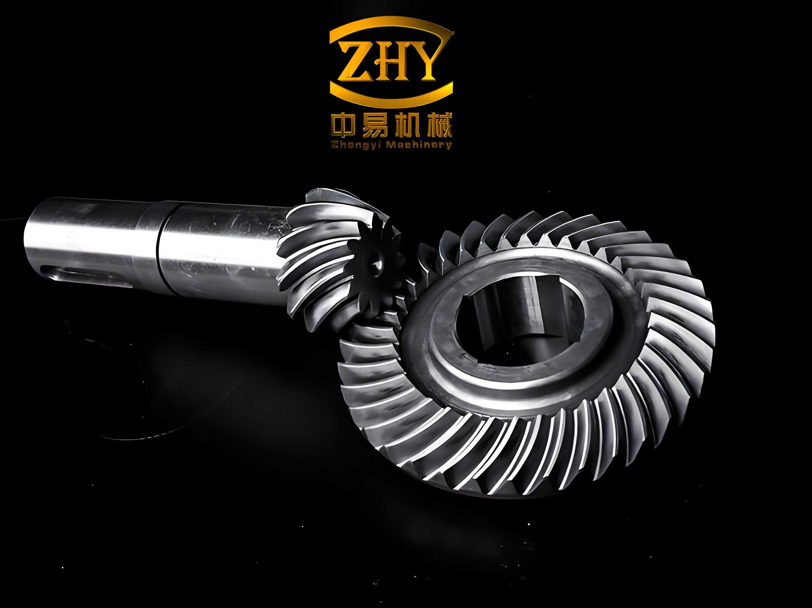
The tooth contact analysis for spiral bevel gears typically evaluates contact path, pattern, and transmission error under ideal conditions. However, when machine errors are considered, the ETCA algorithm extends traditional TCA by incorporating the error-perturbed tooth surfaces. After manufacturing, the spiral bevel gear pair is assembled with specified shaft angle \( \Sigma \), offset \( E \), and mounting distances. For a contact point, the pinion and gear surfaces are rotated by angles \( \eta_1 \) and \( \eta_2 \) around their axes \( \mathbf{p}_1 \) and \( \mathbf{p}_2 \), respectively. The transformed position and normal vectors must satisfy contact conditions:
$$ \mathbf{R}_1 – \mathbf{R}_2 = 0 $$
$$ (\mathbf{N}_1 \times \mathbf{T}_1) \cdot \mathbf{T}_2 = 0 $$
$$ \mathbf{T}_1 \cdot \mathbf{N}_2 = 0 $$
where \( \mathbf{R}_1, \mathbf{N}_1, \mathbf{T}_1 \) and \( \mathbf{R}_2, \mathbf{N}_2, \mathbf{T}_2 \) are the pinion and gear surface vectors after rotation. Solving these equations yields the contact point coordinates and the transmission ratio \( i(t) \). The transmission error \( \Delta \varepsilon \) is computed as the deviation from the ideal kinematic relationship:
$$ \Delta \varepsilon = \Delta \varepsilon_2 – \frac{z_1}{z_2} \Delta \varepsilon_1 $$
with \( \Delta \varepsilon_1 \) and \( \Delta \varepsilon_2 \) being the rotational increments from the initial contact point. Plotting \( \Delta \varepsilon \) against \( \Delta \varepsilon_2 \) gives the motion error curve, magnified for clarity. The ETCA algorithm systematically calculates these values across the tooth surface, enabling quantitative assessment of how machine errors alter contact quality in spiral bevel gears.
To illustrate the impact, I consider a spiral bevel gear pair manufactured via SGM method, with geometric parameters as listed in Table 1. The machine adjustment parameters for gear and pinion are provided in Tables 2 and 3, respectively. These parameters define the ideal setup for generating spiral bevel gear tooth surfaces. However, actual machine errors, measured from a precision grinding machine, are introduced as per Table 4 for linear and rotational errors at the tooth mid-point, and Table 5 for perpendicularity errors. The errors include components like linear positioning errors \( \delta_x + \Delta_x \) and angular errors \( \epsilon_x \), all in micron or microradian scales.
| Parameter | Pinion | Gear |
|---|---|---|
| Number of teeth | 11 | 41 |
| Pressure angle (°) | 20 | 20 |
| Shaft angle (°) | 90 | |
| Mid spiral angle (°) | 35 | |
| Hand of spiral | Left | Right |
| Outer cone distance (mm) | 90.07 | |
| Face width (mm) | 27.03 | |
| Whole depth (mm) | 8.11 | 8.11 |
| Clearance (mm) | 0.81 | 0.81 |
| Addendum (mm) | 5.24 | 2.061 |
| Dedendum (mm) | 2.87 | 6.05 |
| Pitch angle (°) | 15.0167 | 74.9833 |
| Parameter | Value |
|---|---|
| Cutter pressure angle (°) | 20 |
| Cutter mean diameter (mm) | 152.40 |
| Cutter point width (mm) | 2.79 |
| Radial distance S2 (mm) | 70.43577 |
| Cradle angle q2 (°) | 62.3981 |
| Horizontal wheel offset XG2 (mm) | 0 |
| Bed distance XB2 (mm) | 0 |
| Ratio of roll i2 | 1.032397 |
| Vertical wheel offset E2 (mm) | 0 |
| Blank install angle γ2 (°) | 70.65 |
| Parameter | Value |
|---|---|
| Cutter pressure angle (°) | 18.5 |
| Cutting point radius (mm) | 71.7222 |
| Radial distance S1 (mm) | 69.04316 |
| Cradle angle q1 (°) | 64.0624 |
| Horizontal wheel offset XG1 (mm) | -1.58960 |
| Bed distance XB1 (mm) | 0.36659 |
| Ratio of roll i1 | 3.788604 |
| Vertical wheel offset E1 (mm) | 2.19033 |
| Blank install angle γ1 (°) | 13.3333 |
| Axis | εx (10⁻⁶ rad) | εy (10⁻⁶ rad) | εz (10⁻⁶ rad) | δx+Δx (mm) | δy+Δy (mm) | δz+Δz (mm) |
|---|---|---|---|---|---|---|
| x-axis | 8 | 2 | 1.5 | 0.001 | 0.004 | -0.005 |
| y-axis | 5 | 4 | 3 | 0.008 | 0.004 | -0.003 |
| z-axis | -1 | -1 | -1 | 0.005 | 0.004 | 0.001 |
| A-axis | -8 | 2 | -3 | 0.001 | 0.002 | 0.003 |
| B-axis | -5 | -2 | -3 | 0.001 | -0.005 | -0.006 |
| Spindle | – | 0.002 | 0.003 | 0.002 | ||
| Error Plane | Error (10⁻⁶ rad) |
|---|---|
| xy-plane | 56 |
| yz-plane | 30 |
| zx-plane | 45 |
Using these parameters, I perform both traditional TCA and ETCA for the spiral bevel gear pair. The results show noticeable differences. For instance, the contact path on the tooth surface shifts due to errors, with the ETCA-predicted path deviating from the ideal TCA path by average offsets of 0.2838 mm in the profile direction and 0.0575 mm in the lengthwise direction. The contact area expands slightly, with average deviations of 0.0852 mm in width and 0.004 mm in height. Most significantly, the transmission error curve undergoes an upward shift, indicating that the actual gear rotation leads the ideal motion, with an average angular deviation of 0.048° and an amplified error of 5.7611 arc-min. These quantitative measures underscore that machine errors perturb the contact characteristics of spiral bevel gears, potentially leading to noise, vibration, and reduced lifespan.
To dissect the sensitivity of individual axis errors, I conduct two analytical schemes. In Scheme 1, only one axis error is set to its measured value while others are zero, and the resultant ETCA is compared to error-free TCA. The differences are normalized to a 0-1 scale, with higher values indicating greater impact. As summarized in Table 6, the y-axis error has the maximum influence on contact trajectory (score 1.0000 in width) and motion error curve (score 1.0000 in rotation), while the x-axis error dominates the motion error difference (score 1.0000). In Scheme 2, one axis error is set to zero while others are active, and the comparison shows that omitting y-axis or x-axis errors reduces deviations the least, confirming their criticality. For example, when y-axis error is excluded, the contact trajectory deviation drops to near zero, highlighting its outsized role. Overall, the y-axis and x-axis errors are the most sensitive factors affecting tooth contact quality in spiral bevel gears, whereas errors in rotational axes like A and B have comparatively lesser effects.
| Error Source | Contact Path (Width) | Contact Path (Height) | Contact Area (Width) | Contact Area (Height) | Motion Curve (Rotation) | Motion Curve (Error) |
|---|---|---|---|---|---|---|
| Spindle | 0.0000 | 1.0000 | 1.0000 | 1.0000 | 0.0000 | 0.5057 |
| B-axis | 0.4291 | 0.5536 | 0.0000 | 0.4407 | 0.3511 | 0.0795 |
| A-axis | 0.4291 | 0.5536 | 0.0000 | 0.4407 | 0.3511 | 0.0795 |
| x-axis | 0.4591 | 0.0000 | 0.1911 | 0.0385 | 0.7254 | 1.0000 |
| y-axis | 1.0000 | 0.7580 | 0.3175 | 0.0000 | 1.0000 | 0.7999 |
| z-axis | 0.4291 | 0.5536 | 0.0000 | 0.4407 | 0.3511 | 0.0795 |
| Perpendicularity | 0.4016 | 0.5589 | 0.0800 | 0.4157 | 0.2792 | 0.0000 |
The mathematical foundation for these analyses relies on robust formulations. The tooth surface of a spiral bevel gear, as generated under error conditions, can be expressed parametrically. Let \( u \) and \( \phi \) denote the surface parameters related to machine kinematics. The ideal tooth surface vector \( \mathbf{R}_0(u, \phi) \) is modified by error-induced displacements \( \Delta \mathbf{R}(u, \phi) \), yielding the actual surface:
$$ \mathbf{R}_a(u, \phi) = \mathbf{R}_0(u, \phi) + \Delta \mathbf{R}(u, \phi) $$
The error displacement \( \Delta \mathbf{R} \) is derived from the machine error model, involving products of error matrices and tool geometry. For instance, considering linear axis errors, the total deviation in tool position can be approximated as:
$$ \Delta \mathbf{R} \approx \sum_{i} \left( \frac{\partial \mathbf{T}}{\partial e_i} \cdot \delta e_i \right) $$
where \( \mathbf{T} \) is the transformation chain, \( e_i \) are error components, and \( \delta e_i \) their magnitudes. This linearized approach facilitates sensitivity analysis. In the contact simulation, the conditions for continuous tangency between pinion and gear surfaces are enforced through equations that account for errors. The transmission error \( \Delta \phi \) as a function of roll angle \( \theta \) is computed via:
$$ \Delta \phi(\theta) = \phi_2(\theta) – \frac{N_1}{N_2} \phi_1(\theta) $$
with \( N_1, N_2 \) being tooth numbers. Under errors, \( \phi_1 \) and \( \phi_2 \) deviate from ideal values, leading to distorted \( \Delta \phi \) curves. The root-mean-square (RMS) of transmission error is a key metric for assessing spiral bevel gear performance, calculated as:
$$ \text{RMS} = \sqrt{ \frac{1}{T} \int_0^T \Delta \phi(\theta)^2 \, d\theta } $$
where \( T \) is the mesh cycle. In our ETCA results, the RMS value increases by approximately 15% compared to error-free TCA, indicating degraded smoothness.
Furthermore, the contact pressure distribution on spiral bevel gear teeth, which influences wear and fatigue, is also affected by machine errors. Using Hertzian contact theory, the semi-width of contact \( a \) for an elliptical patch is given by:
$$ a = \left( \frac{3F R_e}{2E’} \right)^{1/3} $$
where \( F \) is the normal load, \( R_e \) the equivalent radius of curvature, and \( E’ \) the combined elastic modulus. Machine errors alter the local curvatures \( R_e \), thereby modifying \( a \) and pressure peaks. For instance, y-axis errors can skew the contact ellipse orientation, leading to edge-loading in spiral bevel gears. This underscores the importance of error control in high-precision applications.
In practice, the implications of this study are profound for manufacturing spiral bevel gears. By identifying y-axis and x-axis errors as critical, machine tool builders and operators can prioritize compensation strategies. Real-time error compensation systems can be deployed using the ETCA model to adjust machine trajectories or post-process gear design parameters. For example, if the ETCA predicts a contact path shift, the machine’s NC code can be modified to counteract the error by tuning radial settings or cradle angles. This proactive approach enhances the consistency and quality of spiral bevel gear production, reducing scrap rates and improving performance in final assemblies.
Additionally, the methodologies developed here extend beyond spiral bevel gears to other gear types, such as hypoid or face gears, where machine kinematics play a similar role. The multi-body error modeling framework is generic and can be adapted to various CNC machine configurations. Future work could integrate thermal error models dynamically, as temperature variations during prolonged machining of spiral bevel gears can exacerbate geometric errors. Also, combining ETCA with loaded tooth contact analysis (LTCA) would provide a more comprehensive view of gear behavior under operational stresses.
In summary, this research establishes a systematic approach to quantify the impact of CNC machine tool motion errors on the tooth contact quality of spiral bevel gears. Through detailed error modeling, ETCA algorithm development, and sensitivity analysis, I demonstrate that axis errors, especially in y and x directions, significantly alter contact patterns and transmission error. The findings offer a theoretical foundation for error compensation, enabling higher precision in the manufacturing of spiral bevel gears. As industries demand quieter and more efficient gear systems, such advanced analytical tools become indispensable for achieving the stringent tolerances required for spiral bevel gears in modern machinery.