It is a very complicated and random process that gear evolves from the healthy state of tooth surface to fatigue pitting. Based on the research parameters of gear, such as accurate geometry, motion relationship, fractal and rough surface, the dynamic response of gear without pitting and with pitting is discussed in detail according to the basic theory of correlation analysis (such as energy method, fractal theory and FEM) The influence of fatigue pitting parameters on the system is estimated and evaluated quantitatively. In order to better interpret the evolution process of gear tooth surface from healthy operation to fatigue pitting, and the dynamic response characteristics of gear transmission system in the process of evolution, based on the above theoretical research, a fatigue test bench is further built for relevant experimental research and analysis, so as to improve the evolution process and system response characteristics of gear tooth surface fatigue pitting, and provide reference for the construction of gear pitting The dynamic response characteristic database provides basic data research.
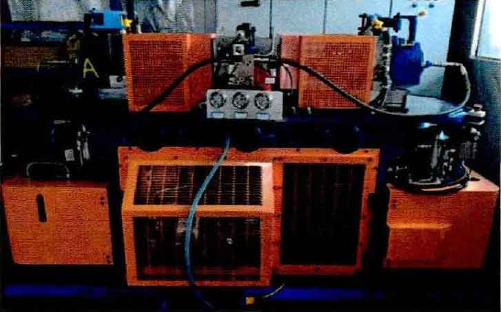
The contact fatigue test-bed of cylindrical gear is shown in Figure 1. This contact fatigue test-bed is a closed power flow test-bed designed by Newcastle University. Compared with the open power flow test-bed, its system has small power consumption and compact space structure, which can achieve better environmental space setting and foundation setting, and is favored by domestic and foreign research teams.
The structural layout of the contact fatigue test-bed is shown in Fig. 2. It can be clearly seen that there are two test gearboxes A and B arranged on the left and right sides respectively, which can realize the experimental research and analysis of two pairs of cylindrical gears at the same time. The gearboxes on both sides are connected by two flexible torsion bars, and the middle is connected by elastic coupling. In addition, in the middle of the test-bed, the driving motor assembly is installed on the active torsion bar, and the torque actuator is installed on the driven torsion bar. The corresponding temperature sensor and speed sensor are arranged near it to measure the temperature and speed of the system and monitor the real-time signal. The layout of the corresponding components is shown in Figure 2.
In order to reduce the additional vibration response of the gear and shaft due to assembly problems, a taper with good concentricity and axial 1:30 is used for assembly. At the same time, the lubrication between the gears in the gearbox adopts direct injection, so as to ensure that the gear meshing position has good lubrication characteristics.


