
In the realm of automotive engineering, the demand for high-performance transmission components has been steadily increasing. Over the past decades, powder metallurgy (PM) has emerged as a cost-effective method for producing complex-shaped parts, such as gears, with minimal material waste and reduced need for machining. However, the mechanical performance requirements, particularly for durability under high loads, have become more stringent. To address this, surface densification techniques, such as gear rolling, have been developed to enhance the density and strength of critical areas like tooth flanks and roots. This study focuses on the application of surface densification to both spiral gears and spur gears, evaluating their feasibility for automotive transmissions. The process involves compaction, sintering, selective densification via rolling, and final heat treatment, aiming to achieve high geometrical accuracy and superior fatigue resistance. Through this research, I explore the potential of combining PM with surface densification to meet the demanding standards of gear quality and performance.
The motivation behind this work stems from the need to expand the applications of PM components in high-stress environments. Traditional PM gears often exhibit porosity that limits their fatigue life, but by selectively densifying the surface, we can mimic the properties of wrought steel while retaining the economic benefits of PM. Spiral gears, in particular, present unique challenges due to their helical geometry, which affects stress distribution and densification uniformity. In this article, I detail the experimental procedures, present results using tables and formulas, and discuss the implications for gear manufacturing. The findings demonstrate that surface densification can significantly improve the mechanical properties of both spiral gears and spur gears, making them viable for demanding automotive applications.
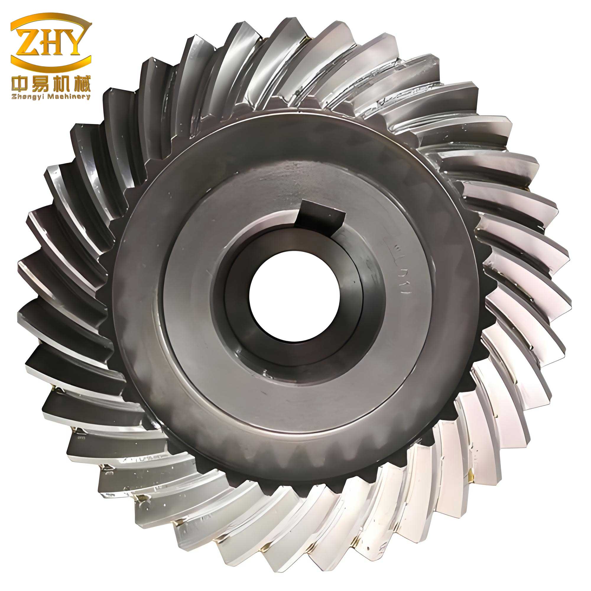
To begin, let me outline the methodology used in this study. The investigation involved two types of gears: spur gears and spiral gears. The gear data are summarized in Table 1, which includes parameters such as number of teeth, normal module, pressure angle, and helix angle. These parameters are critical for understanding the gear geometry and its influence on the densification process. For instance, the helix angle in spiral gears affects the contact pattern and load distribution, which in turn impacts the densification depth and uniformity.
| Parameter | Spur Gear | Spiral Gear |
|---|---|---|
| Number of Teeth (Z) | 20 | 28 |
| Normal Module (mn in mm) | 3.650 | 2 |
| Pressure Angle (αn) | 22.5° | 15° |
| Helix Angle (β) | 0° | 32° |
| Profile Shift Coefficient (x) | 0.471 | 0.136 |
| Ball Diameter (mm) | 89.350 | 74.46 |
The materials selected for the PM gears were based on two powder mixes: Astaloy 85Mo (Fe-0.85Mo) and Astaloy CrLTM (Fe-1.5Cr-0.2Mo), both with low graphite content. For comparison, reference gears made from conventional steels, such as SS92506 (similar to DIN 20NiCrMo2) for spur gears and DIN 16MnCr5 for spiral gears, were used. The chemical compositions of these materials are detailed in Table 2. This table highlights the differences in alloying elements, which influence the sinterability, hardenability, and final mechanical properties of the gears.
| Gear Type | Material | C | Mo | Cr | Mn | Ni | Fe |
|---|---|---|---|---|---|---|---|
| Spur Gears | Reference (SS92506) | 0.20 | 0.20 | 0.55 | 0.50 | 0.55 | Bal. |
| PM Gear (A: Astaloy 85Mo) | 0.28 | 0.85 | – | – | – | Bal. | |
| Spiral Gears | Reference (DIN 16MnCr5) | 0.16 | – | 0.95 | 1.15 | – | Bal. |
| PM Gear (B1: Astaloy CrLTM) | 0.28 | 0.2 | 1.5 | – | – | Bal. | |
| PM Gear (B2: Astaloy 85Mo) | 0.20 | 0.85 | – | – | – | Bal. |
The manufacturing process commenced with the compaction of cylindrical blanks, followed by sintering at 1120°C for 30 minutes in a 90% N2 + 10% H2 atmosphere. The densities of the sintered blanks were approximately 7.15 g/cm³ for spur gears, 7.20 g/cm³ for spiral gears B1, and 7.10 g/cm³ for spiral gears B2. These blanks were then machined via turning and hobbing to achieve pre-forms with slight oversizes, allowing for material allowance during densification. The surface densification was performed using an HC20CN rolling machine, which applies controlled pressure between two dies to compress the tooth surfaces and roots. This process can be described by a simplified model of plastic deformation, where the densification depth (d) relates to the applied stress (σ) and material yield strength (σy):
$$ d = k \cdot \frac{\sigma – \sigma_y}{E} $$
Here, k is a constant dependent on gear geometry, and E is the Young’s modulus. For spiral gears, the helical angle introduces additional complexity, as the stress distribution is non-uniform along the tooth flank. The rolling cycle typically lasts 8–15 seconds, including loading and unloading, making it efficient for mass production.
After densification, the gears underwent heat treatment to enhance surface hardness. For spur gears (A), carburizing was done at 940°C with a carbon potential of 0.8% C, followed by oil quenching and tempering at 160°C. Spiral gears B1 were vacuum carburized at 960°C and quenched in nitrogen gas, while B2 gears were gas carburized at 920°C and oil-quenched. The case depth was defined as the distance from the surface to where hardness reaches 550 HV0.1. This parameter is crucial for fatigue resistance, as it determines the depth of the compressive residual stress layer. The relationship between case depth (Cd) and carburizing time (t) can be approximated by Fick’s law:
$$ C_d = \sqrt{D \cdot t} $$
where D is the diffusion coefficient of carbon in the steel matrix. For PM materials, porosity can affect diffusion paths, but surface densification mitigates this by closing pores near the surface.
Gear quality was assessed using a Klingelnberg P26 3D measuring center, with evaluations based on DIN standards. Key parameters included profile form deviation, helix deviation, and pitch error. The goal was to achieve DIN quality level 8 or better. Additionally, the stability of the process was examined by measuring the scatter in ball diameter and profile deviations before and after rolling. To evaluate mechanical performance, tooth root fatigue tests were conducted on servo-hydraulic machines for spur gears and electromagnetic hydraulic fatigue testers for spiral gears. The load ratio was maintained at 0.1, and run-out cycles were set at 2 million for spur gears and 30 million for spiral gears.
Now, let me present the results. The densification outcomes are summarized in Table 3, which shows the depth of densification for both gear types. Densification depth was defined as the distance from the surface where porosity increases to 2%. For spur gears, the tooth flank densification reached about 0.5 mm, while the root region was slightly less. In contrast, for spiral gears, the root area exhibited deeper densification, up to 0.4–0.5 mm, whereas the tooth flank was around 0.2 mm. This difference can be attributed to the geometry of spiral gears, where the helical teeth cause stress concentration in the roots during rolling. The densification process effectively closes surface pores, increasing density to nearly full density (above 7.2 g/cm³), which is essential for subsequent carburizing.
| Gear Type | Tooth Flank Densification (mm) | Tooth Root Densification (mm) |
|---|---|---|
| Spur Gear (A) | 0.5 | 0.4 |
| Spiral Gear (B1) | 0.2 | 0.5 |
| Spiral Gear (B2) | 0.2 | 0.4 |
The gear quality after rolling is detailed in Table 4. Most parameters met DIN level 8, with some exceeding it. For spur gears, the total profile deviation was 26 μm, slightly above the DIN 8 limit of 25 μm but within DIN 9. Spiral gears B1 achieved DIN 8 or higher across all metrics, demonstrating the effectiveness of rolling in improving geometrical accuracy. The stability of the process was evident from the reduction in scatter for ball diameter measurements. Before rolling, the standard deviation for spiral gears B1 was 0.0225 mm, which decreased to 0.0031 mm after rolling. This indicates high repeatability of the rolling machine. Similarly, profile form deviation showed consistent results, with scatter bands aligning with DIN 7 to 8 levels.
| Quality Parameter | Spur Gear (A) | Spiral Gear (B1) |
|---|---|---|
| Profile Form Deviation (ffα) | 8 | 8 |
| Profile Slope Deviation (FHα) | 6 | 8 |
| Total Profile Deviation (Fα) | 9* | 7 |
| Helix Form Deviation (ffβ) | 7 | 8 |
| Helix Slope Deviation (fHβ) | 7 | 7 |
| Total Helix Deviation (Fβ) | 8 | 7 |
| Single Pitch Deviation (fu) | 6 | 6 |
| Adjacent Pitch Error (fβ) | 7 | 4 |
| Total Cumulative Pitch Error (Fp) | 5 | 5 |
| Runout Tolerance (Fr)** | 7 | 2 |
* Close to level 8 (difference of 1 μm). ** Reference axis based on tooth flanks, not bore.
Surface hardening results are presented in Table 5. For spur gears, the case depth was 1.0 mm, within the target range of 0.7–1.2 mm, and surface hardness exceeded 700 HV0.1. Spiral gears B1 had a case depth of 0.5 mm with surface hardness of 760 HV0.1, while B2 gears achieved 0.35 mm case depth and 850 HV0.1 hardness. These values indicate successful carburizing, aided by the densified surface that prevents gas penetration into pores. The hardness profiles can be modeled using an exponential decay function:
$$ H(x) = H_s \cdot e^{-x / \lambda} + H_c $$
where H(x) is hardness at depth x, Hs is surface hardness, λ is a decay constant, and Hc is core hardness. For spiral gears, the helical geometry may cause variations in case depth along the tooth, but densification ensures uniformity.
| Gear Type | Case Depth (mm) | Surface Hardness (HV0.1) | Core Hardness (HV0.1) |
|---|---|---|---|
| Spur Gear (A) | 1.0 | >700 | ~300 |
| Spiral Gear (B1) | 0.5 | 760 | ~350 |
| Spiral Gear (B2) | 0.35 | 850 | ~320 |
Heat treatment deformation was also analyzed. For spiral gears B1, the profile form deviation remained stable at DIN 8 after rolling and heat treatment, but profile slope deviation changed significantly. This systematic distortion can be compensated by adjusting the rolling process. For instance, by intentionally introducing a profile slope error during rolling, the heat treatment-induced changes can be offset. The relationship between deformation (Δ) and processing parameters can be expressed as:
$$ \Delta = \alpha \cdot T + \beta \cdot t $$
where α and β are coefficients dependent on material and geometry, T is temperature, and t is time. For spiral gears, the helix angle adds complexity, but empirical adjustments in rolling die design can minimize final errors.
Tooth root fatigue tests yielded promising results. For spur gears, the endurance limit was 33 kN, compared to 31 kN for conventional steel gears. For spiral gears B2, the endurance limit was 9.4 kN, close to the 10 kN of reference gears. These values demonstrate that surface densification can enhance fatigue resistance to levels comparable to wrought steel. The fatigue strength (σf) can be estimated using the following formula, which accounts for densification depth (d) and case depth (Cd):
$$ \sigma_f = \sigma_0 \cdot \left(1 + \gamma \cdot \frac{d}{C_d}\right) $$
where σ0 is the base fatigue strength of the PM material, and γ is a factor reflecting the improvement from densification. For spiral gears, the helical teeth may lead to lower stress concentrations, but the densification in root areas is critical for performance.
In the discussion, I reflect on these findings. The densification depth achieved is sufficient for most applications, as it closes pores and allows effective carburizing. Deeper densification might be desirable, but it risks gear fracture during rolling, especially for spiral gears with complex geometry. The gear quality results confirm that rolling can achieve DIN 8 levels, which is acceptable for automotive transmissions. The stability of the process is high, with rolling machine repeatability being a key factor. However, challenges remain in controlling bore runout due to tooling gaps in PM compaction, but this can be addressed by post-heat treatment machining or honing.
The surface hardening process was successful, with case depths meeting targets. For spiral gears, vacuum carburizing of Cr-containing materials prevented oxidation, while gas carburizing worked well for Mo-based alloys. The difference in hardness between B1 and B2 gears highlights the influence of alloy composition on hardenability. In terms of heat treatment deformation, the changes in profile and helix deviations are manageable through process optimization. By tweaking rolling parameters, such as die geometry or center distance, we can pre-compensate for distortions, ensuring final gear quality.
Fatigue performance is a critical metric. The improved endurance limits for both gear types validate the surface densification approach. For spiral gears, the results are particularly encouraging, as they demonstrate that helical gears can benefit from this technique despite their geometrical complexities. The endurance limit for spiral gears B2 was slightly lower than for spur gears, which may be due to factors like root radius variations, surface roughness, or material differences. However, the close match to conventional steel gears suggests that PM spiral gears with surface densification are viable for high-load applications.
To further analyze the data, I propose a model for densification efficiency (η) based on gear geometry and rolling parameters. For spiral gears, the efficiency can be expressed as:
$$ \eta = \frac{d_{\text{actual}}}{d_{\text{theoretical}}} = \frac{1}{1 + \epsilon \cdot \sin(\beta)} $$
where dactual is measured densification depth, dtheoretical is the ideal depth for a spur gear, ε is a material constant, and β is the helix angle. This formula shows that as the helix angle increases, densification efficiency decreases for tooth flanks but may increase for roots due to stress redistribution. This aligns with our observations for spiral gears, where root densification was deeper.
In conclusion, surface densification via rolling is a powerful method for enhancing the performance of PM gears. It allows for selective densification of critical areas, improving fatigue resistance and geometrical accuracy with minimal cost addition. For spiral gears, the process requires careful optimization due to helical geometry, but the results prove feasibility. Future work could explore advanced materials or combined processes, such as shot peening after densification, to further boost performance. Overall, this study underscores the potential of PM and surface densification to meet the evolving demands of automotive transmissions, paving the way for wider adoption of spiral gears in high-stress environments.
Throughout this article, I have emphasized the importance of spiral gears in modern engineering. Their helical design offers smoother operation and higher load capacity, but manufacturing challenges necessitate innovative approaches like surface densification. By leveraging PM techniques, we can produce spiral gears that are both cost-effective and durable, contributing to the advancement of automotive technology. As research continues, I anticipate further refinements in densification processes, leading to even better performance for spiral gears and other complex components.