
In my research I focus on the characterization, measurement, and influence of symmetry deviation in herringbone gears, while keeping the broader metrology problem of the miter gear in view. A miter gear and a herringbone gear both demand careful control of geometric error, but the symmetry problem is especially severe for herringbone gears because two opposite helical gear halves must act as one load-sharing transmission element. When the two halves are not symmetric about the midplane, the load no longer distributes evenly, and the resulting axial force, contact stress, and vibration can become unacceptable in high-speed and heavy-duty systems. My work therefore treats symmetry deviation not as a single scalar value but as a set of distance and angle components that can be measured, computed, and compared with standard gear deviations.
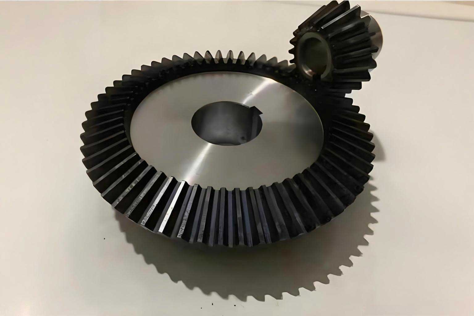
Research Background and Engineering Motivation
Gears are fundamental transmission elements. A miter gear is often used where motion must be turned through an angle, while a herringbone gear is used where high load capacity and low axial force are required. The herringbone gear can be understood as two helical gears with opposite hands joined together. This structure combines the high contact ratio and high load capacity of a helical gear with the advantage that the axial forces from the two halves can cancel each other. For this cancellation to work, the two halves must be as symmetric as possible about the central plane. If the two halves are manufactured with different phase positions, different radial positions, different helix angles, or different profile angles, then the axial forces do not cancel completely. The remaining axial force excites axial vibration, increases tooth contact stress, and may reduce service life.
I found that the existing industrial requirements for herringbone gear symmetry are often expressed only as a tolerance such as “less than 20 µm,” but the meaning of that tolerance is not always clear. In many cases a miter gear inspection plan has well-defined standards, while a herringbone gear symmetry inspection plan does not. This gap is important because a miter gear and a herringbone gear both require traceable measurement, yet the herringbone gear has an additional symmetry condition that a single miter gear does not have. My motivation is therefore to build a bridge between gear error theory and practical coordinate measurement so that symmetry deviation of a herringbone gear can be evaluated in a way that is as clear as the evaluation of profile deviation or helix deviation.
Review of Gear Measurement Technology
Gear measurement technology has developed through several stages. Analytical measurement evaluates individual deviations such as profile deviation, helix deviation, and pitch deviation. Composite measurement uses meshing action to evaluate transmission error and radial composite deviation. Overall error measurement combines individual and composite information to describe the gear as a whole. Coordinate measurement uses a coordinate measuring machine or gear measuring center to sample the tooth surface and compare the measured points with a theoretical surface. Non-contact measurement uses optical or laser sensors to obtain surface data without probe contact.
For a miter gear, coordinate measurement is attractive because the tooth surface is geometrically complex and cannot always be represented by a simple two-dimensional profile. For a herringbone gear, coordinate measurement is even more useful because the two opposite helical halves can be sampled separately and then compared through a symmetry midplane. A miter gear measurement plan often relies on a datum axis, a datum plane, and a set of theoretical tooth surfaces. I adopted a similar logic for the herringbone gear, but I added the symmetry midplane as the central reference. In this way, the measurement of a miter gear and the measurement of a herringbone gear share the same coordinate metrology foundation.
The main measurement methods available to me were point measurement, feature-line measurement, and full-tooth-surface measurement. Point measurement is fast but relies on a few characteristic points and is sensitive to positioning error. Full-tooth-surface measurement is information-rich but time-consuming and complex. Feature-line measurement uses a profile line or a helix line as the characteristic curve. I selected feature-line measurement because it provides enough data to describe symmetry deviation while remaining practical on a coordinate measuring machine. This choice also makes it possible to compare the results with standard profile and helix evaluation methods, which are familiar in miter gear and herringbone gear metrology.
Effect of Gear Error on Transmission Performance
Gear error changes the actual meshing process. A miter gear with profile error may have an instantaneous contact position that differs from the theoretical position. A herringbone gear with symmetry deviation may have one half carrying more load than the other. The consequence is not only a local stress increase but also a change in mesh stiffness, transmission error, and dynamic response. In my review I grouped the effects as follows.
| Error type | Main physical effect | Consequence for miter gear or herringbone gear |
|---|---|---|
| Profile deviation | Departure of actual involute from theoretical involute | Contact ratio change, impact at engagement, stress concentration |
| Helix deviation | Departure of actual helix from theoretical helix | Uneven load along tooth width, edge contact, axial force variation |
| Pitch deviation | Position error of successive teeth | Transmission error, axial displacement in herringbone gear |
| Runout and eccentricity | Geometric center offset | Modulation of mesh stiffness, vibration sidebands |
| Symmetry deviation | Mismatch of the two opposite halves | Unequal load sharing, residual axial force, axial vibration |
The symmetry deviation of a herringbone gear is therefore closely related to the errors that affect a miter gear, but it has a distinct load-sharing character. In a miter gear the error mainly changes the local contact; in a herringbone gear the error can shift the balance between two gear halves. This difference is why a dedicated symmetry deviation characterization is necessary.
Characterization of Herringbone Gear Symmetry Deviation
I began by transforming the symmetry problem into a comparison of two tooth surfaces. The theoretical herringbone gear is symmetric about its midplane. If I mirror one half of the gear about the midplane, the mirrored surface should coincide with the corresponding surface of the other half. Manufacturing error prevents perfect coincidence. Therefore the symmetry deviation can be defined as the deviation between the mirrored surface and the actual opposite surface.
The comparison of two surfaces is exactly the subject of gear error theory. A real tooth surface can deviate from a theoretical tooth surface by a distance and by angular tilts. I decomposed the deviation into a distance component and an angle component. The distance component can be further divided into a circumferential distance and a radial distance. The angle component can be divided into a helix angle deviation and a profile angle deviation. I denote these components as follows:
| Component | Symbol | Meaning |
|---|---|---|
| Circumferential distance deviation | \(L_s\) | Relative phase shift between the two halves about the gear axis |
| Radial distance deviation | \(L_R\) | Relative radial offset of the two corresponding tooth surfaces |
| Helix angle deviation | \(L_\alpha\) | Relative angular tilt along the helix direction |
| Profile angle deviation | \(L_\beta\) | Relative angular tilt along the involute profile direction |
To compute these components I used the average helix and the average profile fitted from measured points. For a helix line, I extended the average helix of the upper and lower halves to the symmetry midplane. The two intersection points generally do not coincide. Their polar coordinates are
$$
R_1=\sqrt{x_1^2+y_1^2},\qquad \phi_1=\arctan\frac{y_1}{x_1}
$$
$$
R_2=\sqrt{x_2^2+y_2^2},\qquad \phi_2=\arctan\frac{y_2}{x_2}
$$
The radial distance deviation is
$$
L_R=|R_1-R_2|
$$
The angular phase difference is
$$
\Delta\phi=\phi_1-\phi_2
$$
Using the reference radius \(r_b\), the circumferential distance deviation is
$$
L_s=r_b\Delta\phi
$$
The helix angle difference is
$$
\Delta\alpha=\alpha_1-\alpha_2
$$
Within the measured face width range \(\Delta Z\), the helix angle deviation expressed as a length is
$$
L_\alpha=\frac{\Delta Z}{\sin\Delta\alpha}
$$
For the profile direction, I fitted the average profile lines of the two corresponding tooth surfaces. I moved them so that their starting points coincided and then measured the angular difference at the end points. If the end radii are \(r_{k1}\) and \(r_{k2}\), and the corresponding polar angles are \(\theta_{k1}\) and \(\theta_{k2}\), then
$$
L_\beta=\max(r_{k1},r_{k2})\,|\theta_{k1}-\theta_{k2}|
$$
These four values provide a more complete description than a single “alignment” or “symmetry” value. In particular, the profile angle deviation can be large even when the helix intersection points are close, and the helix angle deviation can be large even when the radial distance is small. This is why a miter gear inspection that only checks one position may miss the full error state of a herringbone gear.
Measurement Method Using a Coordinate Measuring Machine
I designed the measurement procedure around a coordinate measuring machine. A coordinate measuring machine creates a spatial Cartesian coordinate system and records the position of a probe when it touches the workpiece. For a miter gear or a herringbone gear, the probe is usually a ruby sphere. The probe center is recorded, and the contact point must be corrected by the probe radius. I used a small spherical probe to access the tooth space and avoid interference.
The first task is to establish the datum. For a herringbone gear with an integral shaft, I used a cylindrical surface and a shoulder plane to build the coordinate system. The cylindrical surface defines the gear axis, and the shoulder plane defines the axial reference. The symmetry midplane is then established from symmetric features or from the total face width. If the gear has two shoulder surfaces that are symmetric about the midplane, the midplane can be set halfway between them. If the gear has no convenient symmetric feature, the total face width can be measured and the midplane can be placed at half the face width.
Once the coordinate system is established, I sample the tooth surface along two types of feature lines. The first is the profile line, which is measured in the middle of the face width. The second is the helix line, which is measured near the pitch cylinder. The sampling density can be set to approximately two points per millimeter. For the profile line, I use equal angular increments, equal radial increments, or equal involute length increments. The equal angular method is simple on a coordinate measuring machine because the gear can be indexed by a rotary axis or the points can be generated directly. The equal radial increment method is convenient in polar coordinates. The equal involute length method is convenient for involute evaluation but requires more complex post-processing.
For the helix line, I measure points on the pitch cylinder. If two adjacent points have a small axial separation \(\Delta Z\) and a rotational difference \(\Delta\theta\), then the measured arc length is
$$
\Delta s_i = r_{b0}\Delta\theta_i
$$
The theoretical arc length for the same axial rise is
$$
\Delta s_0 = \Delta Z\tan\beta
$$
The helix deviation in the normal direction is approximately
$$
\Delta f_i = \cos\beta\left(\Delta s_i-\Delta s_0\right)
= \cos\beta\left(r_{b0}\Delta\theta_i-\Delta Z\tan\beta\right)
$$
The profile and helix evaluation then follows the same logic as standard gear deviation evaluation. I fit an average line to the measured points. The total deviation is the distance between two design lines that enclose the measured trace. The form deviation is the distance between two curves parallel to the average line that enclose the measured trace. The slope deviation is the distance between two design lines that intersect the average line at the ends of the evaluation range.
Measurement Program and Data Processing
I divided the software into three parts: datum establishment, data extraction, and data processing. The datum part determines the gear axis and symmetry midplane. The extraction part controls the coordinate measuring machine and records the profile and helix points. The processing part imports the point data into a numerical computing environment and computes the symmetry deviation components.
The measurement program can be represented in a simplified form as follows.
| Step | Action | Purpose |
|---|---|---|
| 1 | Probe qualification | Determine effective probe radius and position |
| 2 | Datum plane and cylinder measurement | Establish coordinate system |
| 3 | Symmetry midplane measurement | Set the axial reference for symmetry |
| 4 | Gear parameter input | Define module, tooth number, pressure angle, helix angle, hand |
| 5 | Profile line scan | Sample involute direction |
| 6 | Helix line scan | Sample helix direction |
| 7 | Opposite half repeat | Sample corresponding surface of the other hand |
| 8 | Data export | Prepare for symmetry computation |
In the processing stage I fit the helix points using a parametric helix equation. For a helix on a cylinder of radius \(r\),
$$
\begin{cases}
x = r\cos\theta\\
y = r\sin\theta\\
z = b\theta
\end{cases}
$$
I fit the parameter \(b\) to the measured points. The average helix is then extended to the symmetry midplane. The intersection point of each average helix with the midplane gives the radial and circumferential information. Similarly, I fit the profile points using the involute equation. The involute is
$$
r_k=\frac{r_b}{\cos\alpha_k}
$$
$$
\theta_k=\tan\alpha_k-\alpha_k=\operatorname{inv}\alpha_k
$$
I use the fitted involute to find the average profile line. The angular difference between the two corresponding average profile lines gives the profile angle deviation.
Experimental Validation
I measured a set of aviation herringbone gears. The gear parameters are listed below. The same procedure can be applied to a miter gear if the datum and symmetry reference are defined appropriately, but the herringbone gear provides a more demanding test because the two halves must be compared.
| Parameter | Value |
|---|---|
| Number of teeth \(Z\) | 27 |
| Normal module \(m_n\) | 3.8788 mm |
| Normal pressure angle \(\alpha_n\) | 22.5° |
| Helix angle \(\beta\) | 30° |
| Tip diameter \(d_a\) | 130.62 mm |
| Root diameter \(d_f\) | 108.51 mm |
| Face width \(b\) | 47 mm |
The coordinate measuring machine had a specified length-dependent accuracy. Before measurement I calibrated the machine with gauge blocks in three axial directions and four spatial diagonals. The maximum permissible error can be written as
$$
E_{\text{MPE}}=2.5+2.8\frac{L}{1000}\ \mu\mathrm{m}
$$
where \(L\) is the measured length in millimeters. The calibration results were within the allowed range. This calibration is important for both miter gear and herringbone gear measurement because any scale error propagates directly into the symmetry components.
| Direction | Gauge length (mm) | Maximum observed error (µm) | Allowed error (µm) | Result |
|---|---|---|---|---|
| X axis | 400 | 2.18 | 3.62 | Pass |
| X axis | 250 | 1.04 | 3.20 | Pass |
| X axis | 200 | 0.92 | 3.06 | Pass |
| X axis | 150 | 0.56 | 2.92 | Pass |
| X axis | 30 | 1.55 | 2.58 | Pass |
| Spatial diagonal 1 | 400 | 0.48 | 3.62 | Pass |
| Spatial diagonal 2 | 250 | 2.36 | 3.20 | Pass |
| Spatial diagonal 3 | 200 | 2.18 | 3.06 | Pass |
After calibration I measured three groups of herringbone gear teeth. Each group included the profile line and helix line of both hands. The measured points were imported into the numerical processing program. I fitted the average helix and average profile for each surface. I then computed the four symmetry components. The results are shown below.
| Group | \(L_s\) (µm) | \(L_R\) (µm) | \(L_\alpha\) (µm) | \(L_\beta\) (µm) |
|---|---|---|---|---|
| 1 | 15.3 | 10.2 | 5.3 | 6.3 |
| 2 | 13.6 | 8.5 | 6.5 | 5.9 |
| 3 | 17.8 | 11.7 | 7.2 | 8.4 |
The largest circumferential distance deviation was 17.8 µm. The design requirement for this gear was that the centering error should remain below 20.0 µm. Therefore the measured result is acceptable. At the same time the radial, helix angle, and profile angle components reveal that the two halves are not simply shifted; they are also tilted. A miter gear inspection that only checks a single point would not reveal this combination.
I also computed the standard helix deviations from the same measured points. The results were close to those obtained from a commercial gear measurement module. This comparison supports the correctness of the extraction and processing method.
| Deviation item | Coordinate measuring result (µm) | Gear measuring module result (µm) |
|---|---|---|
| Total helix deviation | 23.2 | 20.1 |
| Helix slope deviation | 2.9 | 2.5 |
| Helix form deviation | 21.9 | 21.2 |
Error Sources and Compensation
The measured symmetry deviation contains contributions from the gear itself and from the measurement process. I analyzed three main sources: probe radius error, machine geometric error, and datum and positioning error. The probe radius error is caused by the difference between the recorded center of the probe sphere and the actual contact point on the tooth surface. For an involute surface, the compensation can be written as
$$
\begin{cases}
x_0 = x_1 + R_c\cos(\alpha_a+\theta_a)\\
y_0 = y_1 + R_c\sin(\alpha_a+\theta_a)
\end{cases}
$$
where \(R_c\) is the probe radius, \(\alpha_a\) is the pressure angle at the contact point, and \(\theta_a\) is the involute roll angle. I applied this compensation to the measured profile points. The change in the symmetry components was very small. The probe radius mainly shifts the measured point along the normal direction and does not change the fitted average profile angle significantly.
The machine geometric error includes straightness, squareness, scale, and dynamic errors. I compensated the positioning error by using the theoretical tooth surface equation as a constraint. If a measured point should lie on the tooth surface, then the point must satisfy the surface equation. I projected the measured point onto the theoretical surface in the direction normal to the surface. The corrected point is the closest point on the theoretical surface.
For a helical tooth surface, the theoretical point can be written in parametric form. Let \(A_0=(x_0,y_0,z_0)\) be the desired theoretical point and \(A_1=(x_1,y_1,z_1)\) be the actual measured point. Because \(A_1\) lies on the manufactured surface, it must satisfy the surface equation. I solve for the phase difference \(\theta\) and the roll angle \(\phi\) that bring the theoretical point to the measured point. The corrected coordinates are then obtained from
$$
\begin{cases}
x_c = r_b[\cos(\phi+\theta)\cos(\phi+\theta_k)-\sin(\phi+\theta)\sin(\phi+\theta_k)]\\
y_c = r_b[\cos(\phi+\theta)\sin(\phi+\theta_k)+\sin(\phi+\theta)\cos(\phi+\theta_k)]\\
z_c = r_b\cot\beta\,(\phi+\theta)
\end{cases}
$$
After compensation the average distance from the measured points to the theoretical surface decreased. The scatter also decreased. This indicates that the positioning error compensation improves the stability of the symmetry evaluation.
| Group | \(L_s\) before (µm) | \(L_s\) after (µm) | \(L_R\) before (µm) | \(L_R\) after (µm) | \(L_\alpha\) before (µm) | \(L_\alpha\) after (µm) | \(L_\beta\) before (µm) | \(L_\beta\) after (µm) |
|---|---|---|---|---|---|---|---|---|
| 1 | 15.3 | 11.5 | 10.2 | 8.3 | 5.3 | 5.1 | 6.3 | 5.8 |
| 2 | 13.6 | 10.7 | 8.5 | 8.0 | 6.5 | 6.3 | 5.9 | 5.6 |
| 3 | 17.8 | 15.3 | 11.7 | 9.4 | 7.2 | 6.9 | 8.4 | 8.1 |
The compensation reduced the circumferential and radial components by about 1 to 2 µm. The angle components changed less. This is reasonable because the angle components are determined mainly by the shape of the average line rather than by a uniform offset. The result also shows that a miter gear measurement plan should include a similar compensation strategy if the highest accuracy is required.
Influence of Symmetry Deviation on Meshing Behavior
After measuring the symmetry components, I studied how each component affects the meshing behavior. I built a theoretical tooth surface model for the herringbone gear. The model starts from the involute equation and then sweeps the involute along a helix. The standard involute equation is
$$
r_k=\frac{r_b}{\cos\alpha_k}
$$
$$
\theta_k=\tan\alpha_k-\alpha_k
$$
For a helical gear, the tooth surface is generated by rotating and translating the involute along the gear axis. If the rotation angle is \(\gamma\), then the helical surface can be written as
$$
\begin{cases}
x_p = r_b[\cos(\phi_k+\gamma)\cos(\phi_k+\theta_k)-\sin(\phi_k+\gamma)\sin(\phi_k+\theta_k)]\\
y_p = r_b[\cos(\phi_k+\gamma)\sin(\phi_k+\theta_k)+\sin(\phi_k+\gamma)\cos(\phi_k+\theta_k)]\\
z_p = r_b\cot\beta\,\gamma
\end{cases}
$$
To include symmetry deviation, I modified the surface parameters. The circumferential distance deviation \(L_s\) introduces an additional rotation \(\gamma_i\):
$$
\gamma_i=\frac{L_s}{r_i}
$$
The radial distance deviation \(L_R\) changes the base radius:
$$
r_b’=r_b+L_R
$$
The helix angle deviation \(L_\alpha\) changes the helix angle:
$$
\beta_1=\arctan\left(\frac{B\tan\beta+L_\alpha}{B}\right)
$$
The profile angle deviation \(L_\beta\) changes the starting angle of the involute:
$$
\Delta\alpha=\arctan\frac{L_\beta}{L}
$$
$$
\alpha_2=\alpha_1+\Delta\alpha
$$
Combining these effects gives a modified tooth surface equation for the herringbone gear half that contains symmetry deviation. I used this equation to generate finite element models. The models allow me to compare a standard herringbone gear with gears containing one dominant symmetry component at a time.
The finite element model used the following gear parameters.
| Parameter | Pinion | Gear |
|---|---|---|
| Number of teeth | 41 | 44 |
| Normal module | 3.5 mm | 3.5 mm |
| Normal pressure angle | 22.5° | 22.5° |
| Helix angle | 30° | 30° |
| Groove width | 20 mm | 20 mm |
| Face width per half | 30 mm | 30 mm |
I used a finite element contact analysis. The mesh contained approximately 300,000 elements. The contact region was refined to capture the stress distribution. The material properties were those of a typical medium-carbon steel.
| Property | Value |
|---|---|
| Elastic modulus | 210 GPa |
| Poisson ratio | 0.3 |
| Density | 7.8 × 10³ kg/m3 |
| Applied load | 2 kN |
For the standard herringbone gear, the load distribution was symmetric about the midplane. The maximum contact stress was approximately 16,621 N/m². I then introduced each symmetry component separately and increased it by 50% compared with the measured value. The purpose was to observe the sensitivity of the load distribution to each component.
| Component | Measured value (µm) | Increased value (µm) |
|---|---|---|
| Circumferential distance \(L_s\) | 17.8 | 26.7 |
| Radial distance \(L_R\) | 11.7 | 17.6 |
| Helix angle \(L_\alpha\) | 7.2 | 10.8 |
| Profile angle \(L_\beta\) | 8.4 | 12.6 |
The load distribution became asymmetric in every case. One half of the herringbone gear carried more load than the other. This is the central mechanical consequence of symmetry deviation. The maximum stress on the heavily loaded side increased. The following table summarizes the peak stress for each component.
| Case | Maximum stress on heavily loaded side (N/m²) | Increase relative to standard |
|---|---|---|
| Standard herringbone gear | 16,621 | — |
| Circumferential distance \(L_s=17.8\) µm | 16,883 | 1.58% |
| Circumferential distance \(L_s=26.7\) µm | 17,284 | 3.99% |
| Radial distance \(L_R=11.7\) µm | 17,564 | 5.67% |
| Radial distance \(L_R=17.6\) µm | 17,972 | 8.12% |
| Helix angle \(L_\alpha=7.2\) µm | 17,640 | 6.13% |
| Helix angle \(L_\alpha=10.8\) µm | 17,808 | 7.14% |
| Profile angle \(L_\beta=8.4\) µm | 18,986 | 14.2% |
| Profile angle \(L_\beta=12.6\) µm | 20,697 | 24.5% |
The profile angle deviation had the strongest effect on the maximum contact stress. This means that if a herringbone gear must be manufactured to a given symmetry budget, the profile angle component deserves the tightest control. The circumferential distance deviation had the smallest effect on the maximum stress in this study, but it still changes the phase relationship between the two halves and therefore affects axial force cancellation. A miter gear with a similar profile angle error would also experience a stress increase, but the herringbone gear has the additional problem of load sharing between two halves.
Discussion of Measurement Uncertainty and Practical Use
The measurement of symmetry deviation is influenced by the same uncertainty sources that affect any miter gear or herringbone gear coordinate measurement. The largest contributions are the datum axis, the symmetry midplane, the probe radius, the thermal state, and the fitting algorithm. I found that the datum axis is especially important because a small tilt of the axis produces a large apparent helix deviation at the ends of the face width. The symmetry midplane is equally important because a shift of the midplane changes the intersection point of the extended average helix.
To reduce these effects, I recommend the following practical steps for miter gear and herringbone gear inspection:
| Step | Recommendation | Reason |
|---|---|---|
| Datum establishment | Use a long cylindrical surface and a stable shoulder plane | Reduces axis tilt and axial reference error |
| Symmetry midplane | Use symmetric features or total face width | Ensures consistent mirror reference |
| Probe selection | Use a small ruby sphere with proper qualification | Improves access and reduces radius error |
| Sampling density | Use at least two points per millimeter on feature lines | Stabilizes average line fitting |
| Thermal control | Keep the workpiece and machine near 20°C | Reduces scale and drift error |
| Data processing | Fit average helix and average profile separately | Separates distance and angle components |
| Verification | Compare with an independent gear measuring module | Confirms extraction and computation |
These steps apply equally to a miter gear inspection plan. The difference is that for a miter gear the symmetry midplane may not be the central concern, whereas for a herringbone gear it is essential. In both cases, the traceability of the datum and the consistency of the fitting method determine whether the measured deviation can be used for design feedback.
Comparison with Existing Symmetry Concepts
Several existing concepts describe part of the herringbone gear symmetry problem. One concept uses the intersection of the extended helix lines and calls the distance from the intersection to the symmetry plane an alignment deviation. Another uses the midpoint of two corresponding points and calls the distance to the symmetry plane a symmetry deviation. Another uses the contact line and defines a symmetry error from the intersection of the extended contact lines. These concepts are useful, but each emphasizes only one aspect. A miter gear measurement may also use a single reference point or line, but that does not capture the full three-dimensional deviation of the tooth surface.
My four-component characterization is more complete. It separates the radial and circumferential offsets from the helix and profile tilts. This separation is important because different manufacturing causes produce different components. For example, a phase error between the two halves mainly produces circumferential distance deviation. A helix angle error mainly produces helix angle deviation. A profile grinding error mainly produces profile angle deviation. A radial feed error mainly produces radial distance deviation. By reporting all four components, I can give the manufacturing process a more specific feedback signal.
| Concept | Main reference | Reported quantity | Limitation |
|---|---|---|---|
| Alignment deviation | Helix intersection | Distance to symmetry plane | Does not separate radial and circumferential components |
| Symmetry deviation by midpoint | Corresponding points | Distance to symmetry plane | Depends on point selection and does not capture tilt |
| Contact-line symmetry | Instantaneous contact line | Distance from intersection to center plane | Requires contact-line calculation and may be indirect |
| My four-component method | Average helix and average profile | \(L_s,L_R,L_\alpha,L_\beta\) | Requires careful datum and fitting |
This comparison shows why I chose to keep the four components separate. A single value is convenient for a drawing tolerance, but it is not sufficient for diagnosing the cause of the error or for predicting the load distribution. A miter gear drawing may also benefit from a multi-component error report, especially when the miter gear is used in a high-speed transmission.
Finite Element Interpretation and Design Guidance
The finite element results show that symmetry deviation changes the load sharing between the two halves of a herringbone gear. The heavily loaded half experiences a higher contact stress, while the lightly loaded half carries less load. This is equivalent to a loss of load-sharing efficiency. The axial force cancellation is also degraded because the two halves no longer produce equal and opposite axial components.
For a miter gear, the analogous problem is a shift of the contact pattern and a change in the effective contact area. If the miter gear is part of a gear train that also contains a herringbone gear, the symmetry error of the herringbone gear may dominate the axial vibration. This is why I recommend that a transmission system with both a miter gear and a herringbone gear should have separate acceptance criteria for each gear type. The miter gear criterion should focus on contact pattern and transmission error, while the herringbone gear criterion should include the four symmetry components.
The profile angle deviation had the largest influence on the maximum stress. The radial distance deviation had the next largest influence. The helix angle deviation and circumferential distance deviation had smaller but still measurable effects. The order of sensitivity depends on the load level, the face width, and the support stiffness, but the trend is clear: the profile angle component should not be ignored. In many practical inspections, the profile angle is not reported as a separate symmetry quantity. My results show that this omission can hide a significant source of stress increase.
Measurement Procedure Summary
I summarize the complete procedure for herringbone gear symmetry measurement as follows.
| Stage | Task | Output |
|---|---|---|
| Preparation | Clean the gear, stabilize temperature, qualify probe | Ready workpiece and probe |
| Datum | Measure cylinder and shoulder plane | Coordinate system with gear axis |
| Midplane | Measure symmetric features or face width | Symmetry midplane |
| Sampling | Scan profile and helix on both halves | Measured point clouds |
| Fitting | Fit average helix and average profile | Average feature lines |
| Computation | Compute \(L_s,L_R,L_\alpha,L_\beta\) | Symmetry deviation components |
| Verification | Compare standard deviations with independent module | Confidence in result |
| Compensation | Correct probe radius and positioning error | Improved accuracy |
The same table can be adapted for a miter gear by replacing the symmetry midplane with the appropriate miter gear datum and by selecting the tooth surfaces that define the functional contact. For a miter gear, the profile and helix directions may be defined differently, but the principle of separating distance and angle components remains valid.
Limitations and Future Work
My study has several limitations. First, the feature-line method measures only selected profile and helix lines. A full-tooth-surface measurement would provide more information, especially for local contact patterns. Second, the finite element analysis used a static contact model. A dynamic model would be needed to study axial vibration and noise. Third, the symmetry components were measured on a limited number of gear samples. A larger sample would help establish statistical tolerances. Fourth, the miter gear comparison in this work is conceptual rather than experimental. A dedicated miter gear experiment would help generalize the method to other gear types.
For future work I plan to:
| Future direction | Objective |
|---|---|
| Full-surface scanning | Capture local deviations that feature lines may miss |
| Dynamic simulation | Relate symmetry components to axial vibration and noise |
| Miter gear experiment | Validate the multi-component method on a miter gear |
| Statistical tolerance study | Determine meaningful limits for \(L_s,L_R,L_\alpha,L_\beta\) |
| In-process measurement | Enable real-time compensation during manufacturing |
| Standard development | Propose a complete evaluation framework for herringbone gear symmetry |
A miter gear and a herringbone gear are different in geometry, but they share the need for traceable measurement, clear characterization, and a direct link between error and performance. The four-component method I developed for the herringbone gear provides such a link. It turns an ambiguous symmetry condition into measurable quantities. It also provides a basis for comparing a miter gear inspection result with a herringbone gear inspection result when both are used in the same transmission system.
Conclusions
I transformed the symmetry problem of a herringbone gear into a comparison between two tooth surfaces. I decomposed the difference into a circumferential distance deviation, a radial distance deviation, a helix angle deviation, and a profile angle deviation. I derived the calculation formulas for each component using the average helix and average profile. This representation is more complete than a single alignment or symmetry value and is consistent with the logic of miter gear and herringbone gear error evaluation.
I designed a coordinate measuring machine procedure based on feature-line measurement. The procedure includes datum establishment, symmetry midplane determination, profile and helix sampling, average line fitting, and component computation. The measurement program is practical and can be implemented with a spherical probe and a standard coordinate measuring machine. The data processing program computes not only the symmetry components but also the standard profile and helix deviations.
I validated the method with three groups of aviation herringbone gears. The measured circumferential distance, radial distance, helix angle, and profile angle deviations were within the design requirement for the overall centering error. The helix deviations computed from the measured points were close to the results from an independent gear measuring module. I also analyzed probe radius error, machine geometric error, and positioning error. Compensation reduced the circumferential and radial components and improved data stability.
I built a tooth surface equation that includes the four symmetry components and used it in a finite element contact analysis. The results show that symmetry deviation causes uneven load distribution between the two halves of a herringbone gear and increases the maximum contact stress on the heavily loaded side. Among the four components, the profile angle deviation had the largest effect on the maximum stress. This finding provides a clear priority for manufacturing control. The same logic can be extended to a miter gear, where the separation of distance and angle components can improve inspection and design feedback.
Overall, my work provides a characterization method, a measurement method, a data processing method, and a performance evaluation method for herringbone gear symmetry deviation. It supports the development of a unified standard for herringbone gear symmetry and helps improve the reliability of high-speed, heavy-duty gear systems containing both miter gear and herringbone gear elements.