
Gear shaving stands as a highly efficient finishing process extensively utilized in the automotive and machine tool industries for refining gear tooth profiles. Its appeal lies in its high productivity, relatively low cost, and the simplicity of the machine tool design and setup. However, the persistent issue of tooth profile error generated during the gear shaving process remains a central focus of research and practical concern. This error directly impacts the final gear quality, influencing noise levels, transmission efficiency, and service life. This article delves deeply into the dynamic characteristics of the gear shaving process, systematically elaborates on the genesis and transmission mechanisms of profile errors, and explores advanced methodological and technological pathways for their mitigation.
1. Dynamic Characteristics of the Gear Shaving Process
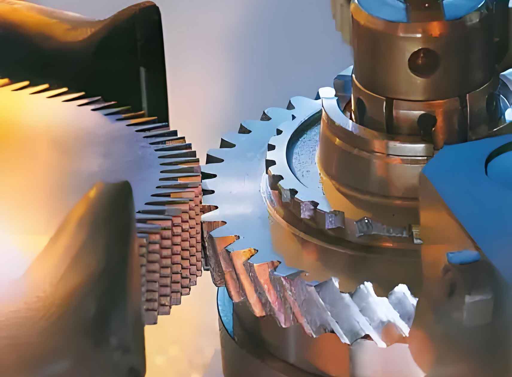
The fundamental principle of gear shaving involves the meshing of the shaving cutter and the workpiece gear with crossed axes, resembling a pair of helical gears in tight mesh, accompanied by a discontinuous cutting and burnishing action. This process is inherently dynamic. Consider the rotational motion of the workpiece gear. Its equilibrium during a steady-state cutting phase is governed by the balance of torques applied by the shaving cutter on the driving and driven flanks of its teeth.
Let $I_{01}$ represent the moment of inertia of the workpiece gear assembly (including its arbor) about its axis $O_1$. The angular acceleration $\frac{d\omega_1}{dt}$ is related to the net torque. The torques arise from the contact forces on the driving flanks (which promote rotation in the direction $\omega_1$) and the driven flanks (which oppose it). The dynamic equation can be expressed as:
$$I_{01} \frac{d\omega_1}{dt} = \sum_{i=1}^{n} M_{01}(F_{d_i}) – \sum_{i=1}^{k} M_{01}(F_{f_i}) – M_{01}(N)$$
where:
$F_{d_i}$ = pressure/cutting force on the $i$-th driving flank contact point,
$F_{f_i}$ = pressure/cutting force on the $i$-th driven flank contact point,
$n$, $k$ = instantaneous number of simultaneous contact points on the driving and driven flanks, respectively, along the lines of action,
$M_{01}(N)$ = resisting torque from friction and other losses.
During stable shaving, the workpiece rotates at a near-constant speed ($\frac{d\omega_1}{dt} \approx 0$), and the resisting torque $M_{01}(N)$ is negligible compared to cutting torques. Thus, the equation simplifies to the condition of torque equilibrium:
$$\sum_{i=1}^{n} M_{01}(F_{d_i}) = \sum_{i=1}^{k} M_{01}(F_{f_i})$$
Assuming the effective moment arm is similar for points on the same line of action, this leads to the simpler force equilibrium:
$$\sum_{i=1}^{n} F_{d_i} = \sum_{i=1}^{k} F_{f_i}$$
Under idealized conditions with uniform contact deformation and no pitch errors, the forces might be equal at each contact point: $F_{d_1}=F_{d_2}=…=F_d$ and $F_{f_1}=F_{f_2}=…=F_f$. The equilibrium condition then becomes:
$$n \cdot F_d = k \cdot F_f$$
This equation reveals the core dynamic interplay in gear shaving: the instantaneous cutting pressure per flank is inversely proportional to the number of contact points on that side of the meshing zone. Since the total contact ratio $\varepsilon_{\gamma}$ is rarely an integer, the numbers $n$ and $k$ fluctuate during rotation, typically varying between two adjacent integers, such that $|n – k| \le 1$. This fundamental fluctuation in contact point population is the primary dynamic driver of profile errors in the gear shaving operation.
2. Root Causes and Mechanisms of Tooth Profile Error in Gear Shaving
The final profile accuracy after gear shaving is not determined by a single factor but is the result of the complex interaction of several distinct yet interrelated mechanisms stemming from the process dynamics described above.
2.1 Profile Error Induced by Fluctuating Contact Points (The “Mid-Case” or “Tooth Profile Sinking” Phenomenon)
This is the most classical and significant source of error in conventional gear shaving. As derived from the force equilibrium $n \cdot F_d = k \cdot F_f$, the instantaneous force per tooth flank varies with the number of contact points. In regions of the tooth profile where the total number of contact points across both lines of action is momentarily higher (typically near the tip and root), the individual flank force $F_d$ or $F_f$ is lower. Conversely, in regions where the total contact count is lower (often around the pitch point or middle of the active profile), the individual flank force is higher.
Since the material removal rate in gear shaving is strongly influenced by the contact pressure, more metal is removed in high-pressure zones and less in low-pressure zones. This differential removal leads to a characteristic error where the tooth profile becomes concave or “sinks” in the middle region. The magnitude of this error is directly related to the amplitude of force fluctuation, which in turn depends on the contact ratio. A lower effective contact ratio exacerbates the force variation and the resulting mid-case concavity.
A simplified model for the instantaneous material removal depth $\Delta z_i$ at a point on the flank can be related to the local force and kinematics:
$$\Delta z_i \propto \frac{F_i \cdot v_{s_i}}{A_c \cdot H}$$
where $F_i$ is the local normal force, $v_{s_i}$ is the local relative sliding velocity, $A_c$ is the effective contact area, and $H$ is the material hardness. The fluctuation in $F_i$, dictated by $n$ and $k$, directly modulates $\Delta z_i$.
2.2 Profile Error Transmission from Pre-Shaving Imperfections
Gear shaving is a corrective process, but its corrective capability is limited and nonlinear. Errors present on the pre-shaved gear are not simply erased; they can be transmitted or amplified. A local deviation (e.g., a depression or protrusion) on the pre-shaved tooth profile alters the local effective base pitch at that meshing point. This pitch deviation disrupts the intended simultaneous contact pattern, causing a localized shift in load distribution among the contacting teeth. This shift can induce an increased or decreased cutting action on other teeth currently in mesh, effectively “copying” or transmitting the original local error to a different location on the gear’s circumference or even onto neighboring teeth. This transmission effect means that the final profile after gear shaving is a convolution of the cutter’s profile, the dynamic contact conditions, and the pre-existing error pattern.
If a local depression on the pre-shaved gear at meshing point $A$ reduces its contact force, the equilibrium condition forces an increase in force at another concurrent contact point $B$. This leads to increased removal at $B$, potentially creating a depression there as well. The transmission can be modeled as a system response. Let $E_{pre}(\theta)$ be the pre-shaving profile error as a function of angular position $\theta$, and $E_{post}(\theta)$ be the post-shaving error. A linearized transmission function $T(\phi)$ (where $\phi$ is a phase shift related to the contact geometry) can describe part of the relationship:
$$E_{post}(\theta) \approx \int T(\phi) \cdot E_{pre}(\theta – \phi) \, d\phi + E_{dyn}(\theta)$$
where $E_{dyn}(\theta)$ is the dynamic error induced by the contact point fluctuation mechanism.
2.3 Profile Error Replication (Re-Registration) from Pre-Shaving Errors
This mechanism is distinct from transmission and is related to the process stiffness. A protrusion on the pre-shaved gear presents a larger initial depth of cut to the shaving cutter teeth. This larger cut generates a proportionally higher cutting force. The gear shaving system (machine, fixture, workpiece, cutter) is not infinitely rigid; it exhibits compliance. Under the higher cutting force at the protrusion, the system deflects more, which reduces the effective depth of cut. Conversely, at a pre-existing depression, the lower cutting force results in less deflection and a more effective cut. This force-deflection feedback loop tends to replicate the original error form onto the finished part. It is analogous to the “error replication” phenomenon in turning or milling. The degree of replication depends on the ratio of system stiffness $K_{sys}$ to the cutting stiffness $K_c$ of the material. The final error $E_{final}$ can be approximated as a fraction of the initial error $E_{initial}$:
$$E_{final} \approx \left( \frac{K_c}{K_{sys} + K_c} \right) E_{initial}$$
A stiff system ($K_{sys} >> K_c$) minimizes replication, while a compliant system allows more of the pre-shaving error to be preserved through the gear shaving operation.
| Mechanism | Primary Cause | Mathematical Relation | Typical Error Pattern |
|---|---|---|---|
| Fluctuating Contact Points | Non-integer contact ratio causing variation in $n$ and $k$. | $n \cdot F_d = k \cdot F_f$; $\Delta z_i \propto F_i$ | Concave “mid-case” sinking near pitch region. |
| Error Transmission | Local pre-shaving errors altering load distribution. | $E_{post}(\theta) \approx \int T(\phi) E_{pre}(\theta-\phi) d\phi$ | Error patterns shifted or mirrored on profile. |
| Error Replication | System deflection under varying cutting forces. | $E_{final} \approx \left( \frac{K_c}{K_{sys} + K_c} \right) E_{initial}$ | Direct replication of pre-shaving highs/lows. |
3. Methodologies for Eliminating and Reducing Profile Errors in Gear Shaving
Controlling the final gear quality requires a holistic strategy that addresses both the preparation of the workpiece and the optimization of the gear shaving process itself, particularly cutter modification.
3.1 Control of Pre-Shaving Gear Quality
The foundation for successful gear shaving is a consistently high-quality pre-shaved gear. The process has limited corrective power for large errors.
- Accuracy Grade: The pre-shaved gear accuracy should generally be within 1 to 1.5 grades of the final required quality. Attempting to shave a gear with excessive error will result in the replication and transmission phenomena dominating the outcome.
- Specific Tolerances: Control over tooth profile error, helix angle error, pitch deviation, and runout is critical. Excessive lead crowning or tip/root modifications pre-shaving can interfere with the intended final form from shaving.
3.2 Optimization of Gear Shaving Cutting Parameters
Cutting parameters significantly influence the dynamic forces, heat generation, and surface finish, thereby affecting profile accuracy.
| Parameter | Typical Range | Influence on Profile Accuracy | Considerations |
|---|---|---|---|
| Cutter Speed ($N_c$) | 90 – 140 rpm (for axial) | Higher speed increases sliding velocity, can improve finish and reduce mid-case error by changing chip formation. | Limited by cutter life, machine power, and dynamic stability. |
| Workpiece Axial Feed ($f_a$) | 70 – 110 mm/min | Moderate to high feed can reduce mid-case error by altering contact duration per stroke. | Very high feed increases roughness; low feed may not stabilize cutting dynamics. |
| Number of Stroke Passes ($P$) | 4 – 6 (roughing), 2 – 4 (finishing) | More passes allow for progressive error correction and stabilization of the cutting process. | Critical for achieving grade 6 or better. Includes roughing and finishing cycles. |
| Radial Infeed | Controlled, often in stages | Final infeed depth directly controls size and final pressure. Must be minimized for finishing. | Often automated with a “no-spark” or final sizing cycle. |
3.3 Strategic Control of Gear Shaving Allowance
The amount and distribution of stock left for gear shaving is paramount. The goal is to provide just enough material to clean up all previous errors and generate the desired finish without excessive cutting that exacerbates dynamic errors.
The ideal distribution is “thicker in the middle, thinner at the ends” of the active profile. This pre-crowning of the stock partially compensates for the anticipated mid-case sinking during gear shaving, as the process will tend to remove more from the thicker central zone. The total allowance depends on module, diameter, and pre-shave quality.
$$ \text{Total Allowance} = A_{\text{base}} + \Delta_{\text{profile}} + \Delta_{\text{lead}} + \Delta_{\text{size}} $$
Where $A_{\text{base}}$ is a minimum allowance for finish, and the $\Delta$ terms are additional stock to correct specific pre-shaving errors in profile, lead, and size, respectively.
| Module (mm) | Typical Allowance (mm) | Notes |
|---|---|---|
| < 3 | 0.06 – 0.12 | Smaller allowance for finer pitches. |
| 3 – 5 | 0.10 – 0.18 | Larger allowance to correct errors from pre-grinding or hobbing. |
| > 5 | 0.15 – 0.25+ | Requires careful process design to avoid excessive force. |
3.4 Precision Cutter Modification (Shaving Cutter Topping)
This is the most powerful and direct method for controlling the tooth profile outcome of gear shaving. By precisely altering the profile of the shaving cutter, the meshing conditions, contact pattern, and pressure distribution between the cutter and workpiece can be optimized to produce the desired final gear profile, effectively compensating for the inherent process errors.
The objective is to design a cutter modification curve $M_c(x)$ (where $x$ is the profile roll distance) such that when convolved with the process dynamics $D$ and the nominal cut $C$, it yields the target gear profile $G_t$ from a given pre-shave profile $G_p$:
$$ G_t = D( C( G_p, M_c(x) ) ) $$
In practice, $M_c(x)$ is determined empirically or via simulation. Common modification strategies include:
- Profile Relief (Tip and Root Relief): Reducing cutter material near the tip and root to decrease contact and cutting pressure in these high-contact zones, mitigating their under-cutting effect relative to the mid-region.
- Intentional Mid-Case Protuberance on Cutter: Adding a slight convexity to the cutter’s active profile. During gear shaving, this convexity preferentially removes more stock from the gear’s mid-region, counteracting the natural sinking tendency. The shape and magnitude are critical.
- Optimized Lead Modification: Modifying the cutter’s helix (lead) to control bias, end relief, or crowning on the gear, which also interacts with the profile generation.
| Technique | Principle | Advantages | Challenges |
|---|---|---|---|
| Traditional Topping (Trial & Error) | Grind cutter based on measured gear errors from previous batches. | Simple in concept, uses empirical data. | Time-consuming, requires skilled technician, not optimal for new parts. |
| Mathematical/Synthetic Topping | Calculate modification based on gear geometry, contact analysis, and error models. | More scientific, can predict outcome. Basis for CNC modification. | Requires accurate models of process dynamics and machine compliance. |
| CNC Topping on Gear Grinder | Use a CNC gear grinder to impart a precisely calculated modification curve onto the shaving cutter. | High precision, repeatability, complex curves possible. | High investment in equipment and software. Dependent on accurate calculation. |
| Copy/Form Topping | Use a master template that embodies the inverse of the desired compensation to guide the cutter grinding. | Effective for stable, high-volume production of a single gear type. | Inflexible. Template creation is an art and requires iteration. |
3.5 Advanced Gear Shaving Process Variations
Beyond parameter tuning and cutter modification, specific process variations have been developed to tackle profile errors:
- Plunge (Radial) Shaving: Eliminates axial feed, can have different contact dynamics that reduce mid-case error for certain gear types.
- Diagonal and Under-Pass Shaving: The cutter travels at an angle relative to the gear axis, changing the contact trace and pressure distribution, often improving profile and lead accuracy.
- Balanced Shaving: A technique involving the sequential shaving of gear flanks with intentional, controlled asymmetries in setup or cutter design to balance cutting forces and system deflection, reducing replication error.
- CNC Shaving with Active Path Control: Modern CNC shaving machines can dynamically alter the radial infeed and center distance during the stroke, actively compensating for predicted or measured errors in real-time.
4. Conclusion and Future Perspectives
The pursuit of high-precision gears via gear shaving necessitates a deep understanding of its nonlinear dynamics, where the fluctuating number of contact points governs instantaneous cutting forces and leads to the characteristic mid-case profile error. This fundamental dynamic interacts with the transmission and replication of pre-existing errors from the workpiece. Achieving superior results therefore relies on a multi-faceted strategy: stringent control of pre-shave quality, optimized process parameters, strategically allocated stock allowance, and, most crucially, the precise modification of the shaving cutter’s profile.
The future of precision in gear shaving lies in the advancement of integrated digital process chains. This includes the development of high-fidelity digital twins that simulate the complete shaving process—incorporating cutter/workpiece geometry, system elastodynamics, and cutting physics—to predict and eliminate errors virtually before physical trials. The output of such simulations will drive closed-loop manufacturing systems, where in-process measurement of gear profile directly informs adaptive CNC paths for the shaving machine and provides data for autonomous optimization of the next cutter re-topping cycle on a CNC gear grinder. Mastering this integration of simulation, sensing, and adaptive control is the key to unlocking the full, consistent precision potential of the gear shaving process for next-generation gear manufacturing.