Abstract:
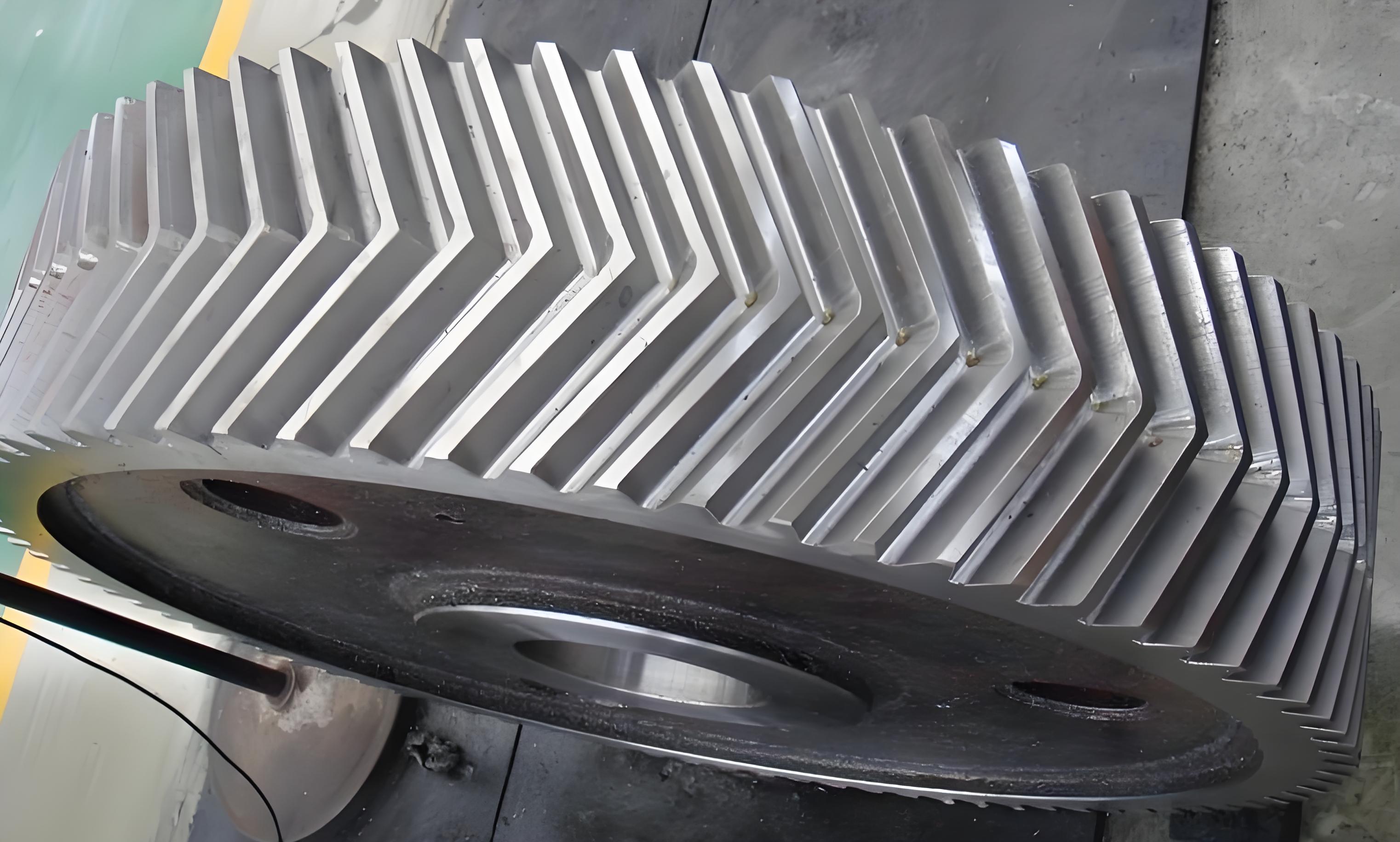
This article introduces a comprehensive gear-making process scheme for large-modulus single-coupling herringbone gear shafts. By leveraging tables, images, and key terms, this summary aims to provide a clear and engaging overview of the process, emphasizing the significance and details of herringbone gear manufacturing.

1. Introduction
Herringbone gear is widely used in engineering machinery, forging equipment, shipping, wind power, and other fields due to their high precision, large carrying capacity, and low transmission noise. However, the complexity of their structure poses significant manufacturing challenges, necessitating specialized equipment, tools, and processes. This article presents a detailed process scheme for manufacturing large-modulus single-coupling herringbone gear shafts.
2. Advantages of Herringbone Gear Transmission
| Advantage | Description |
|---|---|
| High Efficiency | Among the highest in cylindrical gear transmissions |
| Wear Resistance | Large contact area and good wear performance lead to long service life |
| Low Noise | Uniform tooth contact results in reduced transmission noise |
3. Structure and Process Analysis of Herringbone Gear Shafts
Herringbone gear shafts can be classified into two main types: assembled and integral. The integral type, with its one-piece structure of shaft and teeth, offers high torque transmission and precision but is more difficult to process. Based on the width of the relief groove, integral herringbone gear shafts can be further categorized into three structures:
| Structure | Characteristics | Processing Method |
|---|---|---|
| Large Relief Groove | Suitable for hobbing, quenching, and grinding | High precision (GB-6) |
| Small Relief Groove | Generally processed by shaping or slotting; common equipment | Precision (GB-7) |
| No Relief Groove | Compact structure; difficult to process; less commonly used | Milling and profiling |
4. Equipment, Tooling, and Gear-Making Scheme
For large-modulus single-coupling herringbone gear shafts, with a modulus generally ≥14mm and a diameter relatively large, the design requires a tooth accuracy of GB-7 and a tooth surface roughness of Ra 1.6. Based on analysis, this gear shaft belongs to the small relief groove integral herringbone gear shaft, typically processed by shaping and slotting in rough and finish operations. The main processing schemes are as follows:
4.1 Horizontal Processing Scheme
| Step | Equipment | Tooling & Process |
|---|---|---|
| Rough Tooth Cut | Horizontal milling machine or horizontal gear-milling machine; finger milling cutter | Use appropriate tooling to ensure good centering and positioning |
| Finish Processing | Planing machine | Determine tooling, fixture structure, and size based on machine range and part requirements |
4.2 Vertical Processing Scheme
Due to limitations in equipment parameters, some gear shafts exceed the processing range of horizontal machines, necessitating vertical processing equipment.
| Step | Equipment | Tooling & Process |
|---|---|---|
| Rough Tooth Cut | CNC vertical gear-milling machine or general machine tools | Design specialized tooling and fixture for accurate clamping and positioning |
| Finish Processing | Slotting machine | Ensure tooth accuracy reaches GB-7; consider fixture positioning gap and clamping requirements |
5. Summary
This article analyzes the structure and processing equipment for large-modulus single-coupling herringbone gear shafts. By selecting different horizontal or vertical processing equipment based on the part, analyzing processing techniques, specialized tooling, and precautions, and separating rough and finish tooth-cutting operations, the precision requirements of the part’s teeth are met, thereby achieving the gear-making process for large-modulus single-coupling herringbone gear shafts.
