
The overall configuration of the main reducer of a helicopter’s coaxial gear split torsional transmission is shown in Figure 1. The main reducer is the input of two engines. The engines on the left and right sides transmit the power to the input gears on both sides, which are finally collected in the output shaft to drive the main rotor through the intermediate transmission. From the perspective of transmission type, the main reducer can be divided into two parts: the coaxial gear split torque transmission and the planetary gear transmission. In this paper, the research object is the coaxial surface gear split torsional transmission.
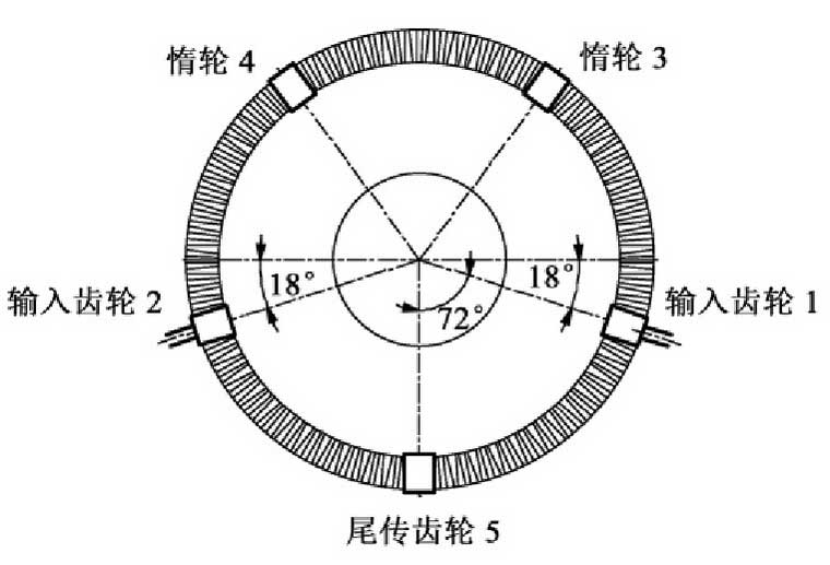
The structure of the coaxial face gear is composed of seven gears (Fig.), which are two input gears, two idler gears, one tail gear and two face gears. Input gear, idler gear and tail transmission gear are straight cylindrical gears, and have the same number of teeth, module, pressure angle and other gear parameters. The upper and lower face gears are orthogonal straight face gears, which also have the same gear parameters. Five cylindrical gears are evenly arranged on the circumference of the face gear, and the angle between the axes of two adjacent cylindrical gears is 72 °.
The input gear is meshed with the upper and lower face gears simultaneously in the coaxial face gear split torque transmission. In an ideal state, the input power is equally distributed to the upper and lower face gears, and the two idler gears and tail transmission gears will re converge the power flowing into the lower face gear to the upper face gear output. The input power is transmitted by several branches at the same time, which has the advantage of reducing the quality of the gear system. However, due to the manufacturing and installation errors and the asymmetry of the stiffness parameters of the configuration itself, the power transferred between parallel branches is not equal, that is to say, there is a problem of uneven load distribution.