
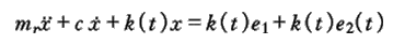
As shown in Figure 1, is the mechanical model of the gear pair, in which the gear has a certain quality, and the gear tooth can be regarded as a spring, so if a pair of gears are taken as the research object, the gear pair can be regarded as a vibration system, and the vibration equation is
X – relative displacement of gears along the action line;
C – gear meshing damping;
K (T) – gear mesh stiffness;
T1, T2 – torque acting on the gear;
R2 – pitch radius of gear;
I – transmission ratio of gear pair;
E (T) – relative displacement of gears in the direction of action line caused by tooth deformation, error and fault;
Mr – converted mass.
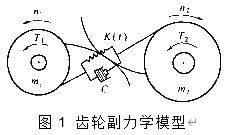
Figure 1 mechanical model of gear pair
mr=m1m2/(m1+m2) (1-2)
If the effect of tooth friction is ignored, (t2-it1) / r2 = 0, e (T) is divided into two parts:
e(t)=e1+e2(t) (1-3)
E1 is the average static elastic deformation of the gear after loading; E2 (T) is the relative displacement between two gears caused by gear error and fault, so it can also be called fault function. This style (1-1) can be simplified as

(1-4)
According to formula (1-4), the vibration of gear is self-excited. The left side of the formula represents the vibration characteristics of the gear pair itself, and the right side is the excitation function. It can be seen from the excitation function that the vibration of the gear comes from two parts: one is K (T) e1, which is independent of the error and fault of the gear, so it is called the normal vibration; the other is K (T) E2 (T), which depends on the comprehensive stiffness and fault function of the gear, which can better explain the existence of the side frequency in the gear signal and the relationship between the side frequency and the fault.
In formula (1-4), the meshing stiffness K (T) of the gear is a periodic variable, which shows that the vibration of the gear is mainly caused by the periodic change of K (T).
The change of K (T) can be explained by two points: one is that the stiffness of a single gear tooth changes with the change of the position of the engagement point; the other is that the number of teeth in engagement changes. For example, for involute spur gears with a coincidence coefficient between 1-2, the single tooth mesh is near the node, and the double tooth mesh is from a certain part on both sides of the pitch line to the tooth top and root (Fig. 2). Obviously, when two teeth mesh, the load of the whole gear is shared by two teeth, so the meshing stiffness of the gear is larger; similarly, the meshing stiffness of the single tooth mesh is smaller.
From the beginning of one gear tooth to the next, the meshing stiffness of the gear changes once. The meshing period and frequency can be calculated. Generally speaking, the change rule of meshing stiffness of gear depends on the coincidence coefficient of gear and the type of gear. The stiffness change of spur gear is steep, while that of helical gear or herringbone gear is gentle, close to sine wave (Fig. 3).
If the speed of the driving wheel of the gear pair is N1 and the number of teeth is Z1; the speed of the driven wheel is N2 and the number of teeth is Z2, then the change frequency of the meshing stiffness of the gear (i.e. the meshing frequency) is
(1-5)
No matter the gear is in normal or abnormal state, this vibration component always exists. But the vibration level of the two states is different. Therefore, the fault diagnosis based on the meshing frequency component of gear vibration signal is feasible. However, due to the complexity of the gear signal, the impact of the fault on the vibration signal is also various, especially due to the role of amplitude modulation and frequency modulation, there are always many side band structures in the gear vibration spectrum, which makes it difficult to use the vibration signal for fault diagnosis.