
The advancement of industrial automation and robotics is fundamentally linked to the development of high-performance, reliable, and precise power transmission components. Among these, the rotary vector reducer, commonly known as the RV reducer, stands out as a critical enabling technology for precision motion control, particularly in the joints of industrial robots. This sophisticated gear system embodies a unique synthesis of planetary and cycloidal drive principles, resulting in a mechanism celebrated for its exceptional compactness, high torque density, remarkable rigidity, and outstanding positional accuracy. As the demand for industrial robots with greater speed, precision, and payload capacity continues to grow globally, the research and optimization of the rotary vector reducer have become paramount. This analysis delves into the structural architecture, kinematic principles, and, most critically, the factors governing the transmission accuracy of the rotary vector reducer, providing a comprehensive overview of its design and performance characteristics.
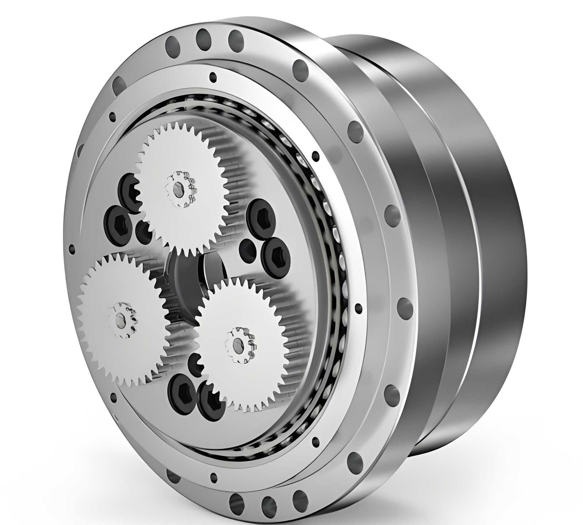
The core mechanical architecture of a standard rotary vector reducer is a two-stage, closed differential system. It ingeniously combines a first-stage planetary gear train with a second-stage cycloidal (or trochoidal) speed reducer. The primary components and their functions are as follows:
1. Input Gear (Sun Gear): This is the high-speed input shaft, typically connected directly to a servomotor. It transmits rotational motion to the first stage.
2. Planetary Gears: Usually three in number, spaced at 120° intervals. They mesh with the central input sun gear. These gears are mounted on and drive the subsequent stage’s crankshafts.
3. Crankshafts (Eccentric Shafts): Equal in number to the planetary gears, each crankshaft is rigidly connected (e.g., via splines or keys) to a corresponding planetary gear. They feature an eccentric section upon which the cycloidal disks are mounted via bearings. The rotation of the planetary gears causes the crankshafts to both rotate on their own axes and revolve around the central axis of the reducer.
4. Cycloidal Disks (RV Gears): Two disks are employed, offset by 180° to balance inertial forces and cancel vibration. They are mounted on the eccentric sections of the crankshafts via needle roller bearings. As the crankshafts rotate, they impart an eccentric, wobbling motion to the cycloidal disks.
5. Needle Gear (Ring Gear): This is a stationary ring (in the most common configuration) with a set of cylindrical pins (needles) arranged radially inwards. The lobed profile of the cycloidal disks meshes with these stationary pins.
6. Output Shaft/Flange: This component is connected to the cycloidal disks via a set of pins or rollers that pass through holes in the disks. It translates the oscillatory motion of the cycloidal disks into slow, continuous rotation.
7. Housing and Bearings: The housing encloses the entire assembly. Large, integrated angular contact bearings directly support the output flange, providing high moment stiffness and eliminating the need for external support structures.
The transmission principle of the rotary vector reducer is key to its performance. Motion transfer occurs in two distinct, cascading stages, as summarized in the kinematic flow below:
Stage 1: Planetary Reduction. High-speed rotation from the motor is input to the sun gear. This drives the three planetary gears, which rotate in the opposite direction. The reduction ratio for this simple stage (with a fixed ring gear, implied by the stationary needle gear housing in the full system) is given by:
$$ i_1 = 1 + \frac{Z_r}{Z_s} $$
where $Z_r$ is the number of teeth on the (theoretical fixed) ring gear and $Z_s$ is the number of teeth on the sun gear. In practice, for an RV reducer, the ring gear of this stage is not physically separate but is functionally linked to the second stage. The planetary gears, fixed to the crankshafts, transmit their reduced speed to the eccentric inputs of the second stage.
Stage 2: Cycloidal Reduction. This is the heart of the rotary vector reducer. The rotating eccentric motion of the crankshafts causes the cycloidal disks to undergo a compound motion: a slow revolution around the central axis (due to the forced eccentric path) and a faster rotation about their own center (due to the meshing with the fixed needle pins). The geometry ensures that for one full revolution of the crankshaft (and thus one “wobble” of the cycloidal disk), the disk itself rotates backward by an angle corresponding to one of its lobes. The reduction ratio is extremely high and is determined by the difference in the number of lobes ($Z_b$) on the cycloidal disk and the number of needle pins ($Z_p$) in the housing:
$$ i_2 = \frac{Z_p}{Z_p – Z_b} $$
Typically, $Z_b = Z_p – 1$, making $i_2 = Z_p$, a very large number. The output shaft pins, passing through holes in the cycloidal disks, pick up only the slow revolutionary component of the disks’ motion, filtering out the faster rotational component.
The total reduction ratio ($i_{total}$) of the rotary vector reducer is the product of the two stages:
$$ i_{total} = i_1 \times i_2 = \left(1 + \frac{Z_r}{Z_s}\right) \times \frac{Z_p}{Z_p – Z_b} $$
This compound design allows for remarkably high single-stage reduction ratios (often from 30:1 to over 200:1) within an extremely compact envelope.
The defining characteristics that make the rotary vector reducer indispensable for robotic applications are derived from its unique design:
| Feature | Description | Benefit |
|---|---|---|
| High Reduction Ratio & Torque Density | Two-stage reduction achieves very high ratios in a single, compact unit. | Enables high torque output from a standard servomotor, perfect for robot joints. |
| High Stiffness & Overload Capacity | Large integrated angular contact bearings directly support the output shaft; multiple teeth share the load simultaneously. | Minimal deflection under load; handles high inertial and shock loads reliably. |
| High Precision & Low Backlash | Multiple tooth engagement in the cycloidal stage (often 50% or more of teeth are in contact) and preloaded bearings minimize lost motion. | Critical for precise positioning, repeatability, and dynamic performance of robots. |
| Compact & Robust Design | The coaxial input/output configuration and integrated bearings save space and reduce part count. | Leads to a more reliable, maintenance-friendly, and easily integrable drive unit. |
| High Efficiency | Power transmission is primarily through rolling contact (bearings on crankshafts, cycloidal disks on needle pins). | Reduces energy loss and heat generation, allowing for continuous high-performance operation. |
Among these, transmission accuracy—encompassing positional precision, repeatability, and minimal backlash—is arguably the most critical performance metric for a robotic rotary vector reducer. Backlash, defined as the lost angular motion between the input and output shafts under zero load, directly translates to positioning error in a robot arm. In a closed-loop control system, excessive backlash can lead to instability, vibration, and reduced path-following accuracy.
The sources of error and backlash in a rotary vector reducer are multi-faceted and originate from manufacturing tolerances, assembly, and operational dynamics. A systematic breakdown is essential for understanding control strategies.
1. Manufacturing Errors:
– Cycloidal Disk Profile Error: Any deviation from the ideal trochoidal tooth profile affects the meshing condition with the needle pins, leading to uneven load distribution and kinematic error.
– Needle Pin & Housing Bore Accuracy: Errors in the position (pitch circle diameter), diameter, and cylindricity of the needle pins and their mounting bores create variable clearance in the cycloidal mesh.
– Crankshaft Eccentricity Error: Inaccuracies in the eccentric journal dimensions or its angular position relative to the main bearing journals affect the phasing and motion of the cycloidal disks.
– Gear Quality (First Stage): Errors in the sun and planetary gear tooth profiles contribute to the overall transmission error spectrum.
2. Assembly-Related Errors:
– Phase Alignment: The two cycloidal disks must be assembled with a precise 180° phase difference. Misalignment disrupts force balance and can increase vibration and error.
– Bearing Clearances: Radial and axial clearances in the crankshaft bearings (needle rollers) and the main output bearings directly contribute to angular lost motion.
– Preload Application: Incorrect preload on the main angular contact bearings can either increase friction (if too high) or allow excessive play (if too low).
3. Operational Factors:
– Elastic Deformation: Under load, all components deform elastically. The deflection of the crankshafts, bending of the output flange, and Hertzian contact deformation at the needle-cycloid interface all contribute to a load-dependent positional error, often termed “torsional stiffness” or “angular compliance.”
– Thermal Effects: Differential expansion of components due to heat generated from friction and losses can alter clearances and preloads, affecting accuracy over time.
The total transmission error or lost motion ($\Delta \theta_{total}$) can be modeled as a composite of these independent error sources. A simplified statistical sum can be expressed as:
$$ \Delta \theta_{total} \approx \sqrt{ (\Delta \theta_{cycloid})^2 + (\Delta \theta_{pin})^2 + (\Delta \theta_{crank})^2 + (\Delta \theta_{bearing})^2 + (\Delta \theta_{elastic})^2 } $$
where each $\Delta \theta_i$ represents the angular error contribution from the i-th source. Controlling $\Delta \theta_{total}$ to within arc-minutes (often less than 1 arc-min for high-precision models) is the central challenge in rotary vector reducer manufacturing.
To achieve and guarantee the high transmission accuracy demanded by modern robotics, a multi-pronged approach is employed throughout the design, manufacturing, and assembly of the rotary vector reducer.
Design Optimization for Accuracy:
– Tooth Profile Modification: The theoretical cycloidal profile is often modified (e.g., through equidistant or offset generation) to accommodate manufacturing tolerances, ensure proper lubrication gaps, and optimize the load distribution among contacting teeth. The modified profile is defined by parameters such as the equidistant offset $r_{rp}$ (roller radius) and the shortening coefficient $K_1$. The parametric equations for a generated profile become more complex than the standard trochoid.
– Stiffness-Oriented Design: Finite Element Analysis (FEA) is used to optimize the geometry of the crankshaft, cycloidal disks, and output flange to maximize torsional stiffness, thereby minimizing $\Delta \theta_{elastic}$ under load.
– Bearing Selection & Integration: Specifying ultra-precision angular contact bearings with controlled preload and minimal runout is non-negotiable.
| Control Strategy | Implementation Method | Target Error Source |
|---|---|---|
| Ultra-Precision Machining | Use of CNC grinding, honing, and gear shaping with sub-micron accuracy. In-process metrology for real-time feedback. | $\Delta \theta_{cycloid}$, $\Delta \theta_{pin}$, $\Delta \theta_{crank}$ |
| Selective Assembly & Phasing | Measuring individual components and matching them into sets (e.g., disks to a specific crankshaft) to compensate for tolerances. Precise angular alignment during assembly. | $\Delta \theta_{assembly}$, $\Delta \theta_{phase}$ |
| Preload Control | Applying a calculated axial preload to the main bearings during final assembly, often using precision spacers or controlled tightening torque. | $\Delta \theta_{bearing}$ (minimizes clearance) |
| Advanced Lubrication & Surface Treatment | Specialized greases for lifetime lubrication and wear reduction. Surface hardening (e.g., carburizing, nitriding) of gears and disks to maintain profile accuracy over the long term. | Long-term stability of $\Delta \theta_{cycloid}$ and wear-induced backlash |
Modern analysis and optimization heavily rely on sophisticated modeling techniques. Multi-body dynamic simulation (MBS) software can model the entire rotary vector reducer, incorporating flexible bodies, non-linear bearing contacts, and the complex meshing of the cycloidal stage. These simulations predict the dynamic transmission error, natural frequencies, and vibration modes, guiding design improvements. Furthermore, the contact force distribution among the needle pins is a critical output of such analysis. The force on the i-th needle pin ($F_i$) is a function of the input torque ($T_{in}$), the reducer geometry, and the manufacturing clearances ($\delta_i$):
$$ F_i = f(T_{in}, Z_p, R_p, \delta_i, E) $$
where $R_p$ is the needle pitch radius and $E$ represents material properties. An uneven distribution indicates poor design or excessive clearances, leading to stress concentrations and accelerated wear, which ultimately degrade accuracy.
In conclusion, the rotary vector reducer represents a pinnacle of precision mechanical engineering, whose performance is foundational to the capabilities of contemporary industrial robots. Its two-stage, cycloidal-based design delivers an unmatched combination of high reduction ratio, compactness, rigidity, and torque capacity. However, its true value in robotics is unlocked by its exceptional transmission accuracy and minimal backlash, attributes that are not inherent but are meticulously engineered. Achieving this requires a holistic focus on ultra-precision manufacturing, intelligent design with profile optimization, controlled assembly processes, and a deep understanding of the system’s dynamics and error sources. As robotics pushes into new domains requiring even greater speed, precision, and reliability, the ongoing research into advanced materials, manufacturing techniques like additive manufacturing for optimized structures, and integrated sensor systems for health monitoring will ensure the rotary vector reducer remains the drive solution of choice for the most demanding precision motion applications.