Principle of slotting
When the gear shaper is used to cut helical gears, it is equivalent to the meshing of a pair of cylindrical gears with parallel axes. The gear shaper is like a gear with a cutting edge formed by grinding the front and back angles. One of the gears in this pair is the workpiece and the other is the gear shaper. During gear shaping, the gear shaper first approaches to the workpiece, and then starts cutting after contacting with the workpiece. During the cutting process, the gear shaper and the workpiece continuously rotate slowly, forming a rolling motion, and ensuring that the gear shaper turns a tooth, the workpiece turns a tooth, or the gear shaper turns a tooth, and the workpiece turns Zn / Zr (Zn – gear number of gear shaper, Zr – gear number of workpiece). At the same time of rolling movement, the gear shaper cutter makes up and down reciprocating fast cutting movement, and gradually cuts out the tooth surface of the processed gear on the gear blank, which is the envelope line of the blade position in the relative movement process of the gear shaper cutter and the gear blank. For the helical gear, because the teeth are “oblique”, when the shaper cutter and the work-piece gear do generating motion, they need to attach a rotation to form a space helix.
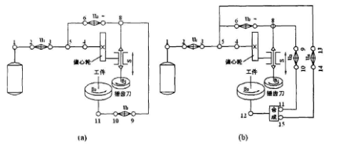
Transmission principle diagram of spiral gear cutting

In the figure, the transmission schematic diagram of slotted spur gear and slotted helical gear are drawn in parallel. Because the radial feed movement and the cutter movement do not affect the formation of the gear surface, they are not shown in the transmission schematic diagram. The transmission chain from point 8 to point 11 in the figure is the transmission chain of rolling and cutting teeth movement, and the transmission chain from point 4 to point 8 is the circular feed transmission chain. The circular feed transmission chain determines the meshing speed of the gear shaper cutter and the gear blank. When the gear shaper tool reciprocates once, the rotation of the gear shaper tool determines the amount of circular feed, which has an impact on the accuracy of generating the involute. Therefore, the circular feed speed is represented by the arc length of the gear shaper tool which rotates on the pitch circle after reciprocating once. From point 1 to point 4 in the figure is the main transmission chain of the machine tool, which determines the reciprocating speed of the gear shaper cutter.
It is known from the previous introduction that since the wire of the helical gear is a helix, the workpiece should have an additional rotation with the straight-line movement of the tool holder during the slotting. Therefore, there should be a transmission link between the tool holder and the workpiece to ensure that when the tool holder moves a lead t in a straight line, the additional rotation obtained by the workpiece is one rotation through the composite mechanism. Because the transmission link is to speed up or slow down the rotating speed of the workpiece through the differential action of the synthesis mechanism, the transmission link is generally called the differential transmission chain. Just as there are strict requirements for the transmission ratio between the tool holder and the main shaft when turning the thread, the transmission ratio between the axial linear movement of the tool holder and the additional rotation of the workpiece is also strict and accurate. Therefore, the nature of differential transmission chain belongs to “internal connection” transmission.
In the transmission schematic diagram, the differential transmission chain is from point 4 to point 12 through 5, 13, 14, 15. The transmission ratio U4 of the displacement mechanism (point 13-14) is adjusted according to the lead t of the workpiece, which belongs to the parameter adjustment of the motion track. In addition, the driving connection of slotted helical gear is the same as that of slotted spur gear. Therefore, through the comparison of figure a and figure B, we can easily see that, compared with slotting spur gear to transmission chain, the transmission chain of slotting helical gear only has one more transposition mechanism (point 13:14), which is usually realized by adding a spiral guide rail in the structure of machine tool.
