
Abstract
Large cylindrical gears are widely used in wind power equipment, mining machinery, ships, and other heavy equipment industries. However, the traditional method of processing these gears on large CNC gear hobbing machines is costly and unsuitable for small to medium-sized enterprises (SMEs). In response to this situation, this paper focuses on the design of an economical gear milling machining NC system for large cylindrical gears, aiming to provide requirements for the development of economical large cylindrical gear processing equipment.
1. Introduction
1.1 Background
Large cylindrical gears play a crucial role in various heavy equipment industries. However, the high cost of processing equipment and specialized tools poses a significant challenge for SMEs. Therefore, there is a need to develop an economical and versatile NC gear milling system for large cylindrical gears.
1.2 Development Status of NC Systems
1.2.1 Research Status of Foreign NC Systems
The development of NC technology in foreign countries has a history of over 60 years, with Europe, the United States, and Japan being the most representative. The global production ratio of low, medium, and high-end CNC machines is 30:60:10. High-end CNC machines are mainly dominated by Germany and the United States, while Japan occupies the main market for medium-end CNC machines. Key foreign CNC system manufacturers include Siemens, FANUC, Mitsubishi Electric, Bosch Rexroth, and Okuma.
With the development of the sixth-generation NC system, PC-based NC systems have become mainstream products. Typical representatives include Sinumerik 840D and 810D, FANUC 0i and 21i series, and Mitsubishi Electric C70 NC system.
1.2.2 Development Status of Domestic NC Systems
(Details omitted for brevity)
1.3 Gear Machining Technology and Trends
1.3.1 Development History of Gear Machining
(Details omitted for brevity)
1.3.2 Trends in Gear Machining Technology and Equipment
- NC Machining
The adoption of NC technology in gear machining machines is increasingly replacing traditional gear machining machines. NC gear machining machines offer advantages such as user-friendly human-machine interfaces, simplified mechanical structures, improved processing accuracy and reliability, and shorter worker training periods.
- High-Speed and High-Efficiency Machining
With advancements in gear machining tool technology, gear machining machines have achieved rapid development in high-speed and high-efficiency cutting. The spindle speed of traditional gear hobbing machines can reach up to 5500 r/min, and the worktable speed can reach 800 r/min.
- High Precision
The adoption of high-rigidity servo motors and drive systems, linear guides, electric spindles, ball screws, and NC technology has improved the processing accuracy of gear machining equipment under high-speed processing conditions.
- Green Manufacturing
(Details omitted for brevity)
- Intelligence
The integration of digital control technology, sensor technology, information technology, and network control technology has significantly enhanced the intelligence of NC gear machining machines. Intelligence is the foundation for improving reliability, safety, stability, complex part processing, precision machining, and unmanned production of gear machines.
1.3.3 Trends in Large Cylindrical Gear Machining Technology
With the rapid development of industries such as wind power equipment, shipbuilding, petroleum machinery, port machinery, high-speed trains, metallurgy, and engineering machinery in China, the demand for large modulus and large diameter gears continues to rise. During the “Twelfth Five-Year Plan” period, large gears and transmission devices were listed as key national development areas. Therefore, further researching and innovating large gear machining technology and improving processing levels have far-reaching significance for the development of China’s large-scale equipment manufacturing industry.
Table 1: Standard Module Series of Cylindrical Gears (GB/T1357-1987)
| Series | Standard Module of Cylindrical Gear (mm) |
|---|---|
| 1st | 0.12, 0.15, 0.2, 0.25, 0.3, 0.35, 0.4, 0.5, 0.6, 0.7, 0.8, 0.9, 1 |
| 2nd | 1.25, 1.5, 1.75, 2, 2.25, 2.5, 2.75, 3, 3.25, 3.5, 3.75, 4, 4.5, 5, 5.5, 6, 6.5 |
| 3rd | 7, 8, 9, 10, 11, 12, 14, 16, 18, 20, 22, 25, 28, 30, 32, 36, 40, 45, 50 |
2. Machining Principles and Methods of Large Cylindrical Gears
2.1 Concept and Forming Principle of Gears
(Details omitted for brevity)
2.2 Gear Machining Methods
The most commonly used gear machining methods are cutting methods, which can be further divided into generative and profiling methods based on the basic principles of tooth profile cutting.
Table 2: Comparison of Common Gear Machining Methods
| Machining Method | Principle | Characteristics | Application |
|---|---|---|---|
| Gear Hobbing | Uses a hob, which is a spiral with a cutting edge, to generate the tooth profile | Continuous cutting, high efficiency | Widely used for rough machining of cylindrical gears |
| Gear Shaping | Directly uses the gear meshing principle to generate and machine gears | Precise control of tooth profile and pitch | Suitable for gears with specific pressure angles and modulus |
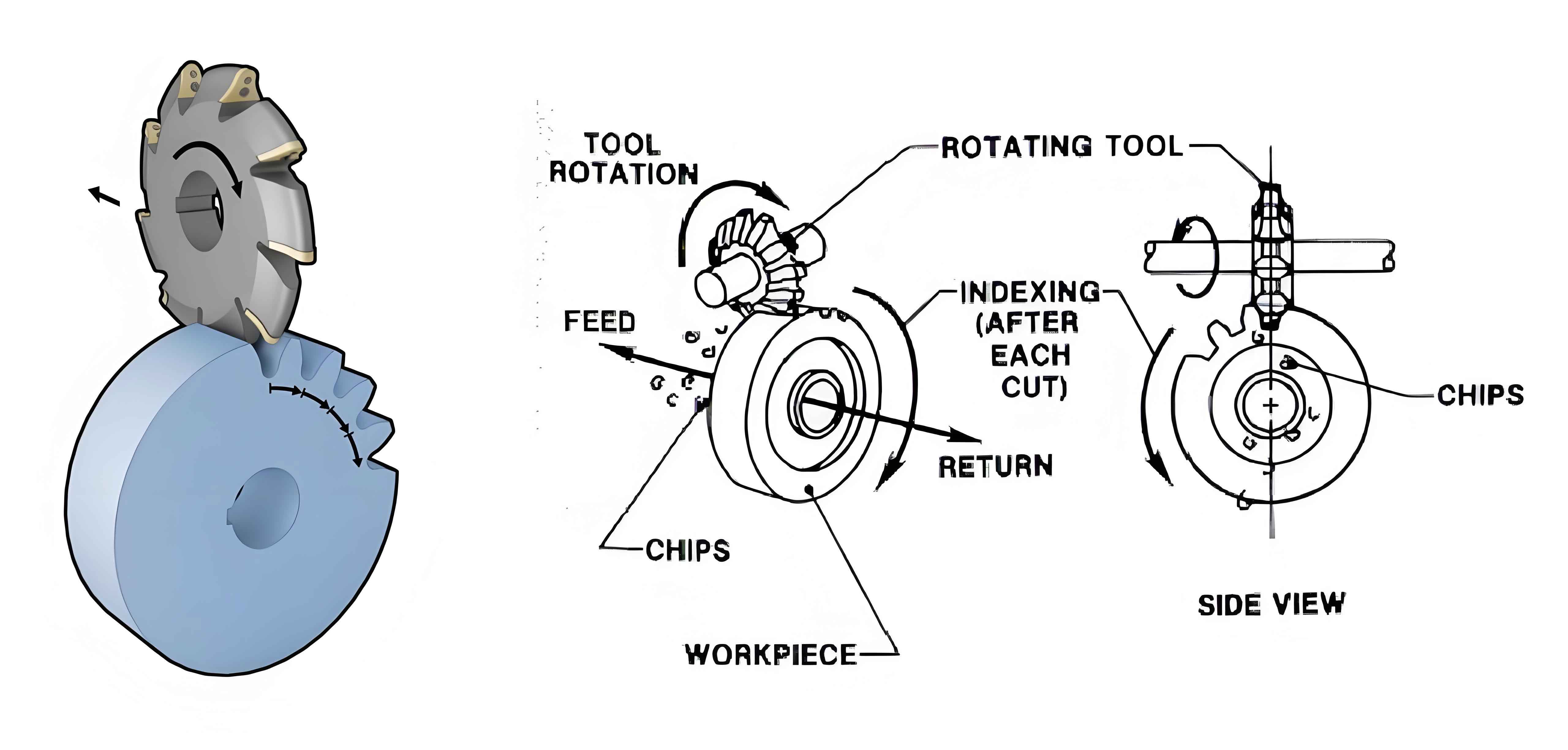
| Gear Milling | Uses forming cutters such as finger gear milling cutters and circular gear milling cutters to directly cut the tooth profile on the gear blank | Simple tool structure, low cost, no need for specialized gear milling machines | Suitable for small batch production or large modulus gear machining |
2.2.1 Application of Generative Methods in Cylindrical Gear Machining
- Hobbing Method
The gear hobbing process involves both a cutting motion and a feeding motion, which together constitute the generative motion. Due to its continuous cutting, gear hobbing is efficient and widely applied.
- Shaping Method
The gear shaping tool can be seen as an external gear with cutting edges. The gear shaping process involves both reciprocating cutting motion and generative motion between the gear shaping tool and the gear blank.
2.2.2 Application of Profiling Methods in Cylindrical Gear Machining
Profiling methods, also known as forming methods, use forming tools to directly cut the tooth profile on the gear blank. Common profiling methods include gear milling and grinding.
- Milling Method
Milling uses forming tools such as finger milling cutters and circular milling cutters to cut the tooth profile directly on the gear blank. Gear milling is suitable for single-piece small-batch production or large modulus gear machining.
- Grinding Method
(Details omitted for brevity)
2.2.3 Design of Digital Machining Methods for Large Cylindrical Gears
Large gears refer to gears with a modulus greater than 12mm or a tooth tip circle radius greater than 250mm. Due to the limitations of machine tool processing ranges and the high cost of specialized hobs, NC gear milling is often used for large cylindrical gears.
This paper focuses on designing an economical, simple, and versatile NC gear milling system for large cylindrical gears. The tooth profile is first digitally designed, and interpolation trajectory coordinate points are calculated. Then, the NC interpolation method is used to complete the machining of large cylindrical gears.
3. Key Technologies of the NC Milling System for Large Cylindrical Gears
3.1 Hardware Structure Design of the NC System
The hardware structure of the NC system is designed on the basis of PC-based NC system principles. It incorporates an Industrial Personal Computer (IPC) and a motion control card as its control core, combined with software modules to collectively form the NC system.
Table 3: Key Components of the NC System Hardware Structure
| Component | Description |
|---|---|
| IPC | Industrial Personal Computer, providing computing power and an operating system platform. It serves as the “brain” of the NC system, responsible for processing various commands, data calculations, and communication with external devices. In this system, the IPC may run the Windows XP operating system, providing a solid foundation for NC system software development and human-machine interface design. |
| Motion Control Card | The motion control card is one of the key hardware components of the NC system. It is responsible for receiving instructions from the IPC and converting them into control signals for servo motors or other actuators. Motion control cards are generally characterized by high speed and high precision, ensuring the stability and processing accuracy of the NC system. In this system, the -400 GT motion control card may be used as the control core, communicating with the IPC through the PCI bus to achieve precise control over gear milling process. |
Apart from the IPC and motion control card, the NC system may also include other critical hardware components such as servo motors, drivers, sensors, etc. These components work together to achieve precise control over gear milling process for large cylindrical gears.
In the design of the hardware structure, consideration must also be given to the circuit connections and communication methods between the components. This system adopts a standard PCI bus communication method, ensuring smooth communication between the various functional modules within the NC system. At the same time, through reasonable circuit design and layout, the stability and reliability of the NC system are improved.
In summary, the hardware structure design of the NC system is the foundation and core of the NC system, determining its performance and processing accuracy. In this system, through reasonable hardware selection and structural design, precise control over gear milling process for large cylindrical gears is achieved.