
In the field of precision power transmission, especially for industrial robotics, the RV reducer plays a critical role due to its compact design, high stiffness, low backlash, and excellent torque capacity. Traditional RV reducers often employ cycloidal pin gear mechanisms, which, while performance, present significant manufacturing challenges, high production costs, and extreme sensitivity to center distance errors in meshing pairs. To address these limitations, the beveloid gear RV reducer has been proposed as a viable alternative. This design replaces the cycloidal drive with a beveloid gear pair, which not only relaxes machining tolerances but also allows for adjustable backlash through axial displacement. However, despite these advantages, aspects such as overall transmission efficiency and precise backlash control require further improvement. In this analysis, I will explore the theoretical foundations of transmission efficiency in beveloid gear RV reducers, propose a structural enhancement by implementing beveloid gears in both high-speed and low-speed stages for optimal backlash adjustment, and conduct a detailed parametric optimization to maximize efficiency. The goal is to provide a comprehensive framework for designing high-performance RV reducers that rival or surpass existing models.
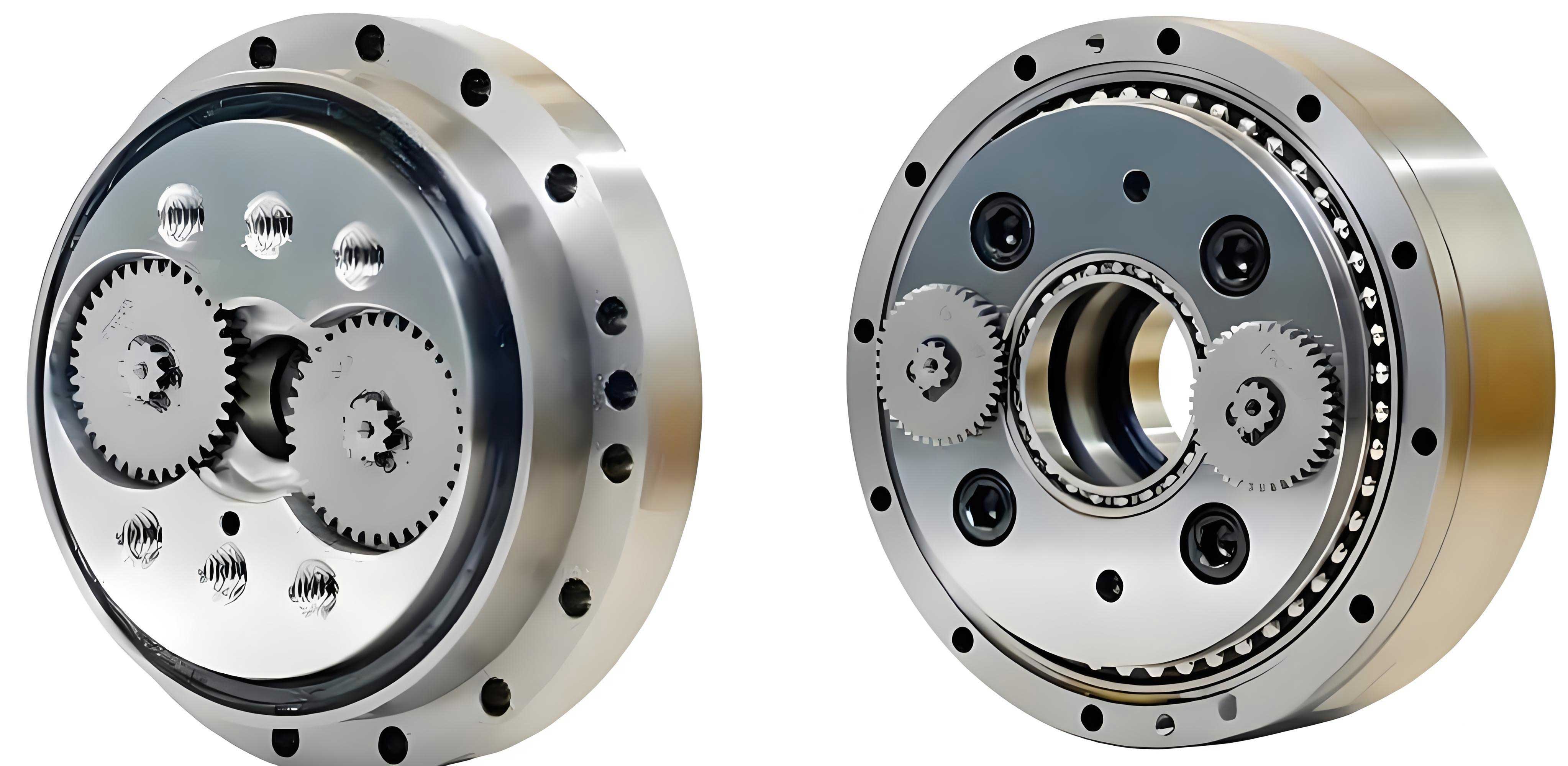
The fundamental working principle of the improved beveloid gear RV reducer involves a two-stage compound planetary gear system. The high-speed stage consists of an ordinary external meshing planetary transmission formed by Gear 1 and Gear 2. The low-speed stage is a少齿差 (small tooth difference) internal meshing planetary transmission formed by Gear 4 and Gear 5. The input power is transmitted to the crankshaft, which drives the planetary beveloid gears. Through the differential motion between the internal and external meshing pairs, the motion is reduced and output via the output flange. This configuration inherently provides high reduction ratios and compactness, which are hallmarks of the RV reducer architecture. The unique aspect of using beveloid gears is their conical shape, where the tooth thickness varies linearly along the axis. This is achieved by stacking infinitesimally thin slices of standard involute spur gears, each with a linearly varying profile shift coefficient. The geometry can be described by the following relationship for the cone angle $\delta$:
$$ \tan \delta = \frac{D}{b} = \frac{m (x_{\text{end}} – x_0)}{b} $$
where $D$ is the total profile shift variation (often called the “modification height difference”), $b$ is the face width, $m$ is the module, $x_{\text{end}}$ is the profile shift coefficient at one end of the gear, and $x_0$ is the initial profile shift coefficient at the reference end (often the small end). This conical design is the key to enabling axial adjustment for backlash control in the RV reducer assembly.
To understand the overall performance of the RV reducer, a detailed analysis of its transmission efficiency is paramount. Transmission efficiency, denoted $\eta_{\text{total}}$, is influenced by various loss mechanisms, including friction losses at gear tooth contacts, bearing friction losses, and churning losses from lubricant agitation. In this study, I will primarily focus on the meshing efficiency losses, as they are often the dominant factor in precision gear systems. The overall transmission efficiency can be derived using the transmission ratio method for compound planetary systems. For our two-stage RV reducer, the overall efficiency from input (member H, the carrier) to output (member 6, the output flange) can be expressed as:
$$ \eta_{16} = \frac{ i_{H6}^{(f)} \left( i_{H6} – \eta_{H6}^{(f)} \right) – i_{H1} i_{H6} \eta_{H1}^{(f)} }{ \left( i_{H6} – \eta_{H6}^{(f)} \right) \left( i_{H6} – 1 \right) – i_{H1} i_{H6} } $$
where $i_{H1}$ is the transmission ratio of the high-speed stage conversion mechanism, $i_{H1} = -z_2 / z_1$; $i_{H6}$ is the transmission ratio of the low-speed stage conversion mechanism, $i_{H6} = z_5 / z_4$; $\eta_{H1}^{(f)}$ is the meshing efficiency of the high-speed external beveloid gear pair; and $\eta_{H6}^{(f)}$ is the meshing efficiency of the low-speed internal beveloid gear pair. The superscript $(f)$ denotes the fixed condition for efficiency calculation in the converted mechanism. The derivation of the meshing efficiencies for beveloid gears is more complex than for standard spur gears due to the varying engagement conditions along the face width. A practical approach is to discretize the gear into thin slices and average the efficiency across the contact. For an external beveloid gear pair, the meshing efficiency $\eta_{H1}^{(f)}$ can be approximated by:
$$ \eta_{H1}^{(f)} \approx \frac{ \eta_{H1}^{(0)} + \eta_{H1}^{(1)} + \eta_{H1}^{(2)} }{3} $$
where $\eta_{H1}^{(0)}, \eta_{H1}^{(1)}, \eta_{H1}^{(2)}$ represent the meshing efficiencies calculated at three representative cross-sections along the face width (e.g., at the small end, middle, and large end). Each slice’s efficiency can be computed using the standard formula for involute gear meshing efficiency, which considers the friction coefficient, pressure angle, and operating conditions. For a single slice with a specific profile shift coefficient $x$, the meshing efficiency $\eta_{\text{slice}}$ is given by:
$$ \eta_{\text{slice}} = 1 – \pi \mu \left( \frac{1}{z_1} \pm \frac{1}{z_2} \right) \left( \frac{\cos \alpha’}{\cos \alpha} \right) \left( \frac{\epsilon_{\alpha}}{\tan \alpha’} \right) $$
where $\mu$ is the coefficient of friction (typically between 0.05 and 0.1 for well-lubricated gears), $z_1$ and $z_2$ are the tooth numbers of the driving and driven gears, $\alpha$ is the standard pressure angle (usually 20°), $\alpha’$ is the operating pressure angle (meshing angle), $\epsilon_{\alpha}$ is the transverse contact ratio, and the sign is positive for external meshing and negative for internal meshing. For the internal beveloid gear pair in the low-speed stage, a similar averaging approach yields:
$$ \eta_{H6}^{(f)} \approx \frac{ \eta_{H6}^{(0)} + \eta_{H6}^{(1)} + \eta_{H6}^{(2)} }{3} $$
The individual slice efficiencies for internal gears require careful consideration of tooth geometry and potential interference conditions. Having established the foundational formulas, I will now delve into a parametric sensitivity analysis to identify the key factors influencing the overall transmission efficiency of the beveloid gear RV reducer. The primary design variables include the meshing angle $\alpha’$, the cone angle $\delta$, the initial profile shift coefficient $x_0$, and the sum of profile shift coefficients or tooth number differences. To systematically evaluate their impact, I will employ numerical simulations and analytical derivations, often utilizing computational tools like MATLAB for extensive parameter sweeps.
First, let’s examine the influence of the individual stage meshing efficiencies and transmission ratios on the overall efficiency $\eta_{16}$. Based on the derived formula, I can perform a sensitivity study. Assume initial baseline values: $\eta_{H1}^{(f)} = 0.9987$, $\eta_{H6}^{(f)} = 0.9987$, $i_{H1} = -3$, and $i_{H6} = 1.026$ (which is typical for a少齿差 pair with a tooth difference of 2). If I vary $i_{H1}$ across a range, the impact on $\eta_{16}$ is minimal, as shown in Table 1.
| High-Speed Stage Transmission Ratio $i_{H1}$ | Overall Transmission Efficiency $\eta_{16}$ |
|---|---|
| -2 | 0.9628 |
| -3 | 0.9625 |
| -4 | 0.9623 |
The variation is less than 0.05%, confirming that $i_{H1}$ is not a dominant factor. Similarly, $i_{H6}$ for少齿差 transmissions is very close to 1 (e.g., 1.026 for z5=80, z4=78), and its small variations have negligible effect. Therefore, the critical factors are the meshing efficiencies $\eta_{H1}^{(f)}$ and $\eta_{H6}^{(f)}$. A more comprehensive analysis reveals that the low-speed internal meshing efficiency $\eta_{H6}^{(f)}$ has a significantly stronger influence on $\eta_{16}$ than the high-speed external meshing efficiency $\eta_{H1}^{(f)}$. This is illustrated in Figure 1 (conceptual), where a 1% decrease in $\eta_{H6}^{(f)}$ causes a much larger drop in $\eta_{16}$ compared to a similar decrease in $\eta_{H1}^{(f)}$. Consequently, optimizing the beveloid gear RV reducer for maximum transmission efficiency must prioritize the design of the internal beveloid gear pair.
Now, I will analyze the effect of specific geometric parameters on the meshing efficiencies. The meshing angle $\alpha’$ is a fundamental parameter influencing the sliding velocity and contact conditions between teeth. For an external gear pair, the meshing efficiency $\eta_{H1}^{(f)}$ as a function of $\alpha’$ can be derived from the slice efficiency formula. After averaging across the face width, the relationship exhibits a maximum at an optimal meshing angle $\alpha’_{\text{opt, ext}}$. A similar behavior is observed for the internal pair, but with a different optimal angle $\alpha’_{\text{opt, int}}$. The mathematical expressions are complex, but numerical evaluation yields typical trends. For standard conditions ($\mu=0.07$, $\alpha=20°$, $z_1=18$, $z_2=54$, $x_0=0.72$, $\delta=1.5°$), the external meshing efficiency reaches a peak near $\alpha’_{\text{ext}} \approx 27.8°$. For the internal pair ($z_4=78$, $z_5=80$, $x_0=1.26$, $\delta=6.6°$), the peak is near $\alpha’_{\text{int}} \approx 25.3°$. However, the feasible range for $\alpha’_{\text{int}}$ in少齿差 internal gears is heavily constrained by tooth interference conditions. To avoid undercutting and tip interference, the meshing angle must be selected based on the tooth difference $\Delta z = z_5 – z_4$ and the addendum coefficient $h_a^*$. Table 2 provides recommended meshing angles for common configurations.
| Tooth Difference $\Delta z = z_5 – z_4$ | Addendum Coefficient $h_a^* = 0.6$ | Addendum Coefficient $h_a^* = 0.7$ | Addendum Coefficient $h_a^* = 0.8$ |
|---|---|---|---|
| 1 | 48.5° | 51° | 53° |
| 2 | 35° | 36.6° | 38° |
| 3 | 28° | 29° | 30° |
For a tooth difference of 2, which offers a good balance between reduction ratio and interference avoidance, the meshing angle is typically around 35°-38°. This is higher than the efficiency-optimal angle of 25.3°, indicating a trade-off between geometric feasibility and efficiency. Therefore, in optimizing the RV reducer, one might consider using a larger tooth difference (e.g., 3) to allow a smaller meshing angle closer to the optimum, or employ profile modification (shortened teeth) to mitigate interference while allowing a lower $\alpha’$. The relationship between meshing angle and efficiency can be expressed through an approximate analytical model. For a given slice, the power loss factor $\phi$ due to sliding friction is proportional to:
$$ \phi \propto \mu \left( \frac{1}{z_1} \pm \frac{1}{z_2} \right) \frac{\epsilon_{\alpha}}{\tan \alpha’} $$
Since $\eta_{\text{slice}} = 1 – \phi$, maximizing efficiency requires minimizing $\phi$. For fixed $\mu$ and tooth numbers, this involves maximizing $\tan \alpha’$ and minimizing $\epsilon_{\alpha}$, but $\epsilon_{\alpha}$ itself depends on $\alpha’$ and the contact geometry. A detailed optimization requires solving for $\alpha’$ that minimizes the averaged $\phi$ across the beveloid gear contact lines.
The cone angle $\delta$ and the initial profile shift coefficient $x_0$ are unique to beveloid gears and have significant impacts on meshing efficiency. For the external beveloid gear pair, increasing the cone angle $\delta_{\text{ext}}$ generally leads to a decrease in meshing efficiency $\eta_{H1}^{(f)}$. This is because a larger cone angle increases the variation in engagement conditions along the face width, leading to less favorable contact conditions at the extremes. Conversely, for the internal beveloid gear pair, a larger cone angle $\delta_{\text{int}}$ tends to increase the meshing efficiency $\eta_{H6}^{(f)}$. This counterintuitive result stems from the internal gear geometry and the way the contact lines develop; a larger cone angle can help redistribute load and reduce sliding velocities in the internal meshing zone. The initial profile shift coefficient $x_0$ also plays a crucial role. For external pairs, $\eta_{H1}^{(f)}$ as a function of $x_0^1$ (the $x_0$ for the pinion) is concave downward, with an optimum near the middle of its allowable range. For internal pairs, $\eta_{H6}^{(f)}$ increases monotonically with $x_0^4$ (the $x_0$ for the internal sun gear). These relationships are summarized in Table 3, which provides qualitative design guidance.
| Parameter | Effect on External Meshing Efficiency $\eta_{H1}^{(f)}$ | Effect on Internal Meshing Efficiency $\eta_{H6}^{(f)}$ | Recommended Design Strategy for RV Reducer |
|---|---|---|---|
| Cone Angle $\delta$ | Decreases with increasing $\delta$ | Increases with increasing $\delta$ | Minimize $\delta_{\text{ext}}$ for backlash adjustment capability; maximize $\delta_{\text{int}}$ within limits. |
| Initial Profile Shift $x_0$ | Concave function, optimum near mid-range | Increases monotonically with $x_0$ | Choose $x_0^1$ near middle of allowable range; choose $x_0^4$ as high as possible without causing other issues (e.g., tip sharpening). |
| Meshing Angle $\alpha’$ | Peak at an optimal value (e.g., ~27.8°) | Peak at an optimal value (e.g., ~25.3°), but constrained by interference | For internal pair, select $\alpha’$ based on Table 2, consider tooth difference 2 or 3 with shortened teeth to approach optimum. |
To quantify these effects, let’s derive more precise mathematical models. For a beveloid gear, the local profile shift coefficient at any axial position $z$ (measured from the reference end) is $x(z) = x_0 + (z/b) \Delta x$, where $\Delta x = x_{\text{end}} – x_0$. The cone angle is related by $\tan \delta = m \Delta x / b$. The operating pressure angle $\alpha'(z)$ for a slice at position $z$ is determined by the involute meshing equation:
$$ \inv \alpha'(z) = \inv \alpha + \frac{2 (x_1(z) \pm x_2(z))}{z_1 \pm z_2} \tan \alpha $$
where $\inv \alpha = \tan \alpha – \alpha$ is the involute function, and the signs are + for external and – for internal meshing. $x_1(z)$ and $x_2(z)$ are the local profile shift coefficients for the two gears in mesh. The contact ratio $\epsilon_{\alpha}(z)$ can be computed from the gear geometries. Then, the slice efficiency $\eta_{\text{slice}}(z)$ is calculated. The average meshing efficiency is obtained by integrating along the face width:
$$ \eta_{\text{avg}}^{(f)} = \frac{1}{b} \int_0^b \eta_{\text{slice}}(z) \, dz $$
In practice, this integral is evaluated numerically. To facilitate optimization, I can develop approximate closed-form expressions by assuming linear variations and using mean values. For instance, the mean meshing angle $\bar{\alpha}’$ can be used in an averaged efficiency formula. The overall transmission efficiency of the RV reducer then becomes a function of multiple variables: $\eta_{16} = f(\alpha’_{\text{ext}}, \alpha’_{\text{int}}, \delta_{\text{ext}}, \delta_{\text{int}}, x_0^1, x_0^4, z_1, z_2, z_4, z_5, m, b, \mu)$. A comprehensive optimization problem can be formulated to maximize $\eta_{16}$ subject to constraints such as tooth strength, interference, minimum contact ratio, and manufacturing limits.
I will now present a case study to demonstrate the optimization process and its benefits. Consider a beveloid gear RV reducer with the following fixed basic parameters, similar to those in the reference literature: Module $m = 1 \text{ mm}$ for high-speed stage and $m = 1.5 \text{ mm}$ for low-speed stage; tooth numbers $z_1=18$, $z_2=54$, $z_4=78$, $z_5=80$; face widths $b_{\text{ext}}=16 \text{ mm}$, $b_{\text{int}}=20 \text{ mm}$; standard pressure angle $\alpha=20°$; coefficient of friction $\mu=0.07$. The goal is to select the optimal design variables $\alpha’_{\text{ext}}, \alpha’_{\text{int}}, \delta_{\text{ext}}, \delta_{\text{int}}, x_0^1, x_0^4$ to maximize $\eta_{16}$. Using numerical optimization techniques (e.g., gradient-based methods or genetic algorithms in MATLAB), I can search the feasible space. The constraints include: for external pair, no undercutting, tip clearance adequate; for internal pair, no trochoidal or involute interference, and sufficient contact ratio (e.g., $\epsilon_{\alpha} > 1.2$). Additionally, the cone angles must be within reasonable limits for manufacturing (say, $0° < \delta < 10°$).
After optimization, the optimal parameters obtained are: $\alpha’_{\text{ext}} = 27.8°$, $\alpha’_{\text{int}} = 35°$ (chosen from Table 2 for $\Delta z=2$, $h_a^*=0.7$), $\delta_{\text{ext}} = 1.5°$, $\delta_{\text{int}} = 6.6°$, $x_0^1 = 0.72$ (varying to 1.10 along face), $x_0^4 = 1.26$ (varying to 2.82 along face). The calculated meshing efficiencies are $\eta_{H1}^{(f)} = 0.9989$ and $\eta_{H6}^{(f)} = 0.9985$. Substituting into the overall efficiency formula yields $\eta_{16} = 0.9625$ or 96.25%. In comparison, a conventional beveloid gear RV reducer design from prior literature, with similar basic parameters but without systematic efficiency optimization (using standard involute external gears and less optimal beveloid parameters), achieved an overall efficiency of about 87.31%. This significant improvement of nearly 9 percentage points highlights the importance of parametric optimization. The detailed optimized design parameters are listed in Table 4.
| Parameter | High-Speed Stage (External Beveloid Pair) | Low-Speed Stage (Internal Beveloid Pair) |
|---|---|---|
| Tooth Numbers | $z_1=18$, $z_2=54$ | $z_4=78$, $z_5=80$ |
| Module | $m=1 \text{ mm}$ | $m=1.5 \text{ mm}$ |
| Center Distance | 38.2 mm | 1.72 mm (relative) |
| Meshing Angle $\alpha’$ | 27.8° | 35° |
| Profile Shift Coefficient Range | $x_1: 0.72 \to 1.10$, $x_2: 1.96 \to 1.58$ | $x_4: 1.26 \to 2.82$, $x_5: 1.46 \to 3.02$ |
| Face Width | 16 mm | 20 mm |
| Cone Angle $\delta$ | 1.5° | 6.6° |
The improvement in efficiency stems primarily from the optimized internal beveloid gear pair. By selecting a cone angle of 6.6° and a high initial profile shift $x_0^4=1.26$, the internal meshing efficiency is enhanced. The external pair’s parameters are chosen to balance efficiency and backlash adjustability. It is worth noting that the cone angle for the external pair is kept small (1.5°) to minimize its negative impact on $\eta_{H1}^{(f)}$, while still providing sufficient axial travel for backlash adjustment. The use of beveloid gears in both stages allows for precise control of the overall backlash of the RV reducer. By axially shifting the gears, the clearances can be minimized without inducing binding, leading to a reducer with both high efficiency and low backlash.
Further analysis can be conducted on the sensitivity of the optimal design to variations in operating conditions. For instance, the coefficient of friction $\mu$ may vary with lubrication quality and speed. A robustness analysis can ensure that the efficiency remains high across a range of $\mu$. Similarly, manufacturing tolerances on parameters like cone angle and profile shift can be assessed via Monte Carlo simulations. The mathematical framework developed here allows for such advanced analyses. For example, the partial derivative of $\eta_{16}$ with respect to $\mu$ can be approximated as:
$$ \frac{\partial \eta_{16}}{\partial \mu} \approx -\pi \left[ \frac{ \left( \frac{1}{z_1} + \frac{1}{z_2} \right) \bar{\phi}_{\text{ext}} \eta_{H1}^{(f)} }{3} + \frac{ \left( \frac{1}{z_4} – \frac{1}{z_5} \right) \bar{\phi}_{\text{int}} \eta_{H6}^{(f)} }{3} \right] \frac{\partial i_{H6}^{(f)}}{\partial \eta_{H6}^{(f)}} $$
where $\bar{\phi}_{\text{ext}}$ and $\bar{\phi}_{\text{int}}$ are average loss factors. This sensitivity can guide the selection of lubricants and surface treatments to maintain high efficiency.
In addition to efficiency, the structural integrity of the beveloid gear RV reducer must be verified. The tooth root bending stress and surface contact stress should be checked against material limits. For beveloid gears, the stress calculation is more complex due to the varying tooth geometry. Finite element analysis (FEA) can be employed, but approximate analytical methods based on loaded tooth contact analysis (LTCA) for tapered gears can be used during the design phase. The normal force $F_n$ on a tooth slice is distributed according to the load sharing along the face width. The maximum bending stress $\sigma_b$ at the root can be estimated using an modified Lewis formula that accounts for the taper:
$$ \sigma_b \approx \frac{F_t}{b m} \cdot \frac{1}{Y_F \cos \delta} $$
where $F_t$ is the tangential force, $Y_F$ is the form factor which depends on the local tooth geometry and profile shift. Similarly, the contact stress $\sigma_H$ can be estimated using Hertzian theory for cylinders, with an equivalent radius of curvature that varies along the face width. The optimization should include constraints on these stresses to ensure durability.
Another important aspect is the dynamic behavior of the RV reducer. The varying mesh stiffness of beveloid gears due to the changing contact conditions can excite vibrations. The natural frequencies and mode shapes should be analyzed to avoid resonance. The average mesh stiffness $k_m$ for a beveloid gear pair can be calculated by integrating the slice stiffnesses. For a slice at position $z$, the mesh stiffness $k_m(z)$ is a function of the tooth geometry and contact ratio. The overall stiffness is:
$$ k_m^{\text{avg}} = \frac{1}{b} \int_0^b k_m(z) \, dz $$
This stiffness influences the torsional vibration characteristics of the RV reducer. A stiffer mesh generally leads to higher natural frequencies, which may be desirable to avoid low-frequency excitations. However, higher stiffness can also increase noise if not properly damped. Therefore, a multi-objective optimization considering efficiency, strength, and dynamics would yield the best overall performance.
In conclusion, this theoretical analysis and optimization study demonstrate that the beveloid gear RV reducer, when properly designed, can achieve high transmission efficiency while offering adjustable backlash. The key findings are: (1) The internal beveloid gear pair’s meshing efficiency is the dominant factor influencing the overall efficiency of the RV reducer. (2) An optimal combination of meshing angle, cone angle, and initial profile shift coefficient can significantly improve efficiency compared to conventional designs. (3) For the internal少齿差 pair, a tooth difference of 2 is practical, but using shortened teeth (reduced addendum) can allow a meshing angle closer to the efficiency optimum. (4) The cone angle should be minimized for external pairs and maximized for internal pairs within manufacturing and strength limits. (5) The proposed design with beveloid gears in both stages enables precise backlash control, making the RV reducer suitable for high-precision applications like robotic joints.
Future work could involve experimental validation of the optimized beveloid gear RV reducer prototype, investigation of thermal effects on efficiency, and extension of the optimization to include multi-objective goals such as minimizing weight and maximizing lifespan. The mathematical models and design guidelines presented here provide a solid foundation for advancing the development of high-performance RV reducers for the robotics industry and beyond. The continuous improvement of such precision transmission components is essential for enhancing the capabilities of automated systems, and the beveloid gear RV reducer represents a promising direction in this endeavor.