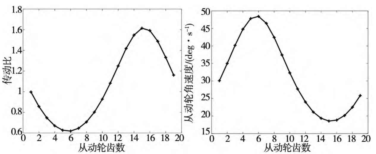
Analyze each tooth of the meshing diagram of the driving wheel and driven wheel, number each tooth, as shown in Figure 1, measure the distance from the rotation center of the driving wheel and driven wheel to each tooth, and the angular velocity of the driven wheel is ω 2 = ω 1 / i12, the results are shown in the table. The angular velocity of the driving wheel is the same as that of the test, which is 30 ° / s. here, for the sake of table simplicity, only the data of some teeth are listed. Note: here, the unit of the angular velocity of the driving wheel and the driven wheel is ° / s. Draw the corresponding relationship between the transmission ratio and the angular velocity of the driven wheel in the table and the driven gear teeth. The results are shown in Fig. 2 and Fig. 3.
| Meshing tooth | Driving wheel / mm | Driven wheel / mm | Transmission ratio | Driving wheel angular speed | Angular velocity of driven wheel |
| Slave 8 master 1 | 24.103 | 24.041 | 0.997 | 30 | 30.077 |
| Slave 6 master 3 | 27.564 | 20.593 | 0.747 | 30 | 40.155 |
| Slave 4 master 5 | 29.600 | 18.573 | 0.627 | 30 | 47.811 |
| Slave 2 master 7 | 29.279 | 18.913 | 0.646 | 30 | 46.443 |
| Slave 19 master 9 | 26.749 | 21.444 | 0.802 | 30 | 37.422 |
| Slave 17 master 11 | 23.139 | 25.041 | 1.082 | 30 | 27.721 |
| Slave 15 master 13 | 19.921 | 28.263 | 1.418 | 30 | 21.145 |
| Slave 13 master 15 | 18.421 | 29.755 | 1.615 | 30 | 18.573 |
| Slave 11 master 17 | 19.358 | 28.805 | 1.488 | 30 | 20.161 |
| Slave 9 master 19 | 22.284 | 25.875 | 1.161 | 30 | 25.837 |
It can be seen from Fig. 2 that the theoretical transmission ratio of non-circular gear is compared with the transmission ratio i12 to be realized( φ 1 ) = 1. 118 + 0. 5sin( φ 1) through comparison, it is found that the graphics are basically consistent. By observing Fig. 3, it can be concluded that the theoretical angular velocity of the driven wheel is basically consistent with the angular velocity curve of the driven wheel obtained by ADAMS simulation. Through the analysis of Figure 2 and figure 3, it is well proved that the method of designing non-circular gear in this paper is correct.