
In the field of gear design and analysis, the traditional methodology for evaluating the meshing performance of tooth surfaces is known as Tooth Contact Analysis (TCA). While powerful, TCA is fundamentally a numerical approach that requires extensive iterative calculations based on specific machine-tool settings to generate its results. This presents a significant limitation during the initial stages of gear design, particularly when employing active tooth surface design methodologies where the tooth surface geometry is defined directly without prior knowledge of the manufacturing machine parameters. Consequently, it is impossible to conduct meshing analysis using conventional TCA while the tooth surface parameters are being designed. To bridge this gap and enable concurrent design and meshing analysis, and to fundamentally reveal the meshing laws governing point-contact tooth surfaces, it is imperative to establish a set of theoretical calculation formulas for point-contact tooth surface meshing analysis. This work provides a comprehensive theoretical framework for such analysis.
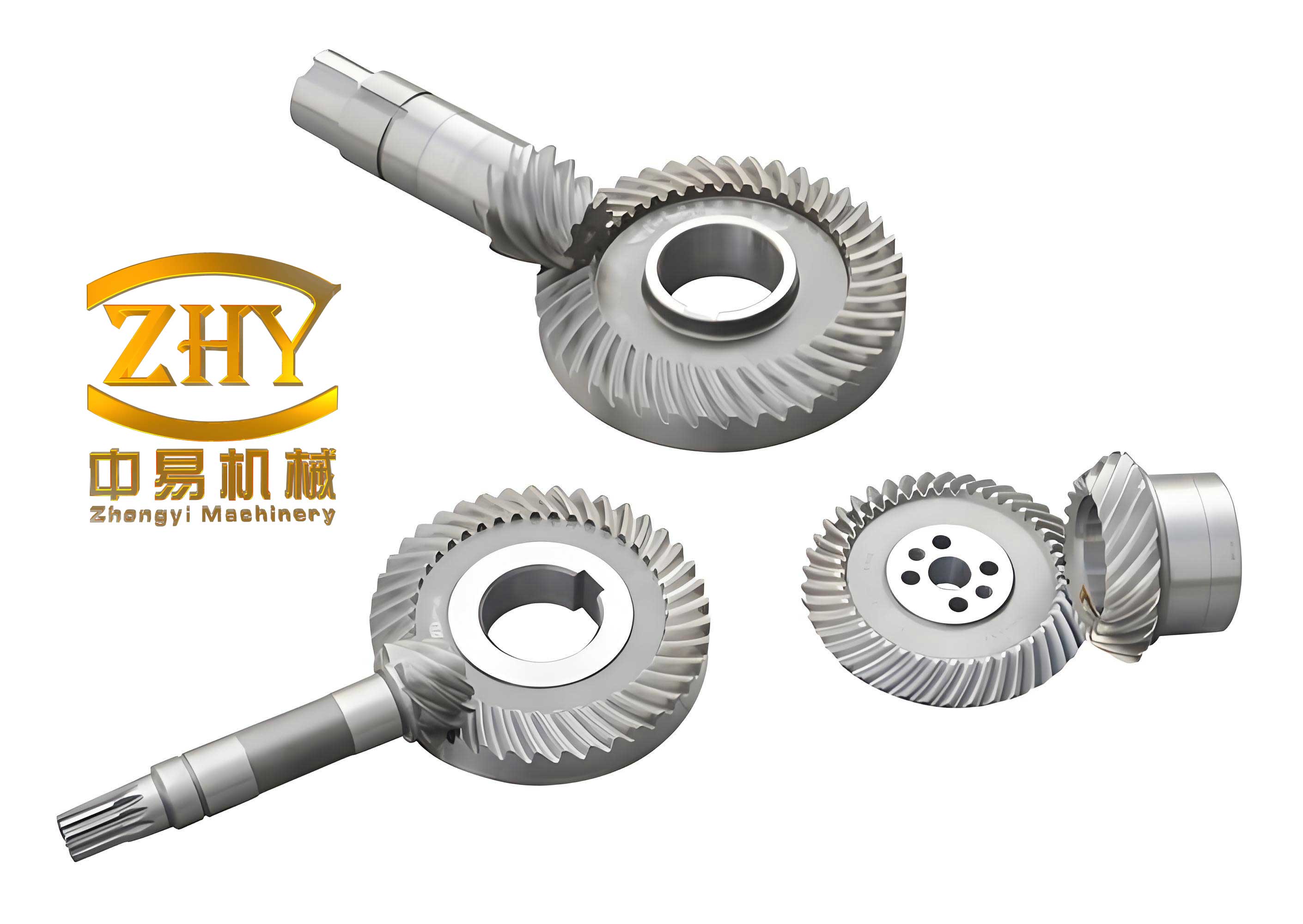
The formulas derived and presented here are integral to the theory and technology of active tooth surface design. They are distinguished by their independence from specific machine-tool adjustment parameters. Instead, they rely solely on the position of the contact point relative to the gear pair and the first-order (tangent plane) and second-order (curvature) properties of the tooth surfaces at that point. This generality makes them applicable to any contact point on the meshing tooth surfaces of hypoid gears. These theoretical tools allow for a clear elucidation of the mismatch mechanism in point-contact gear pairs, offering crucial guidance for their design. The following sections detail the theoretical derivation, present the key formulas, and explore their implications through parametric studies.
Theoretical Framework and Coordinate Systems
The analysis considers a pair of mating tooth surfaces, denoted as Σ₁ (pinion) and Σ₂ (gear), in point contact at a point M. The fundamental requirement for contact is that the surfaces share a common point and possess a common normal vector at that point. To describe the geometry and kinematics, several coordinate systems and vectors are defined.
Let coordinate systems S₁ and S₂ be rigidly attached to the pinion and gear, respectively, with origins O₁ and O₂ located arbitrarily on their respective axes. The unit vectors along the pinion and gear axes are denoted as e₁ and e₂. The shaft angle is Σ, where cos Σ = e₁ · e₂. The shortest distance line between the two axes has a unit vector e, perpendicular to both e₁ and e₂. The angles between e₁, e₂ and e are θ₁ and θ₂.
The position vectors are defined as follows: r₁ is the vector from O₁ to contact point M expressed in S₁; r₂ is from O₂ to M in S₂; R₁ is from O₁ to the origin of the fixed frame; R₂ is from O₂ to the fixed frame origin. The distance from O₁ to the point on the pinion axis closest to the gear axis is a. The distance from that point to O₂ along the gear axis is B. The offset distance (hypoid offset) is E. The parameters a, B, E, θ₁, and θ₂ define the relative installation position of the gear pair and are termed the “installation parameters.”
At the contact point M, the common unit normal vector is n. Within the common tangent plane, two orthogonal unit vectors τ and η are defined, satisfying τ × η = n. The second-order properties of surface Σi are its normal curvatures in the τ and η directions, denoted as κτ(i) and κη(i), and its geodesic torsion in the τ direction, denoted as τgτ(i).
The location of the contact point M on the tooth surfaces is a function of the five installation parameters and the rotational angle of the pinion, φ₁. Therefore, the meshing kinematics are also a function of these six variables (five installation parameters and φ₁). The following formulas establish the relationships between differential changes in these variables and the resulting changes in contact point location and transmission ratio.
Core Theoretical Formulas for Meshing Analysis
1. Formulas for Displacement of the Contact Point on the Tooth Surface
The condition for continuous contact is expressed by the vector equation:
$$\mathbf{r}_1(\varphi_1) + \mathbf{R}_1 = \mathbf{r}_2(\varphi_2) + \mathbf{R}_2$$
Differentiating this equation and the condition for a common normal (n₁ = n₂), and employing the relationships between absolute and relative differentials of vectors, yields formulas for the displacement of the contact point on the tooth surfaces. Let δlτ(i) and δlη(i) represent the displacements of the contact point on surface Σi along the τ and η directions, respectively, due to differential changes in the variables.
The general form of the solution can be structured as follows. For a differential change in pinion rotation dφ₁ and installation parameters da, dB, dE, dθ₁, dθ₂, the resultant displacement on surface Σ₁ is:
$$
\begin{bmatrix}
\delta l_\tau^{(1)} \\
\delta l_\eta^{(1)}
\end{bmatrix} =
\frac{\partial \mathbf{l}^{(1)}}{\partial \varphi_1} d\varphi_1 +
\frac{\partial \mathbf{l}^{(1)}}{\partial a} da +
\frac{\partial \mathbf{l}^{(1)}}{\partial B} dB +
\frac{\partial \mathbf{l}^{(1)}}{\partial E} dE +
\frac{\partial \mathbf{l}^{(1)}}{\partial \theta_1} d\theta_1 +
\frac{\partial \mathbf{l}^{(1)}}{\partial \theta_2} d\theta_2
$$
where $\mathbf{l}^{(1)} = (l_\tau^{(1)}, l_\eta^{(1)})^T$. Each partial derivative term is a 2×1 vector representing the sensitivity of the contact point location on Σ₁ to a unit change in that specific variable. Analogous formulas exist for displacements on surface Σ₂.
The explicit expressions for these sensitivity coefficients involve only the position vectors r₁, r₂, R₁, R₂, the directional vectors e₁, e₂, e, τ, η, n, and the second-order properties κτ(i), κη(i), τgτ(i). They are completely independent of any machine-tool settings. A subset of these coefficients, specifically $\partial l_\eta^{(1)} / \partial \varphi_1$ and $\partial l_\tau^{(1)} / \partial \varphi_1$, directly defines the direction of the contact path on the pinion tooth surface Σ₁. This is a crucial parameter in tooth surface design.
| Symbol | Description | Role in Formulas |
|---|---|---|
| $\delta l_{\tau, \eta}^{(i)}$ | Displacement on surface Σi along τ/η. | Dependent variable, output of analysis. |
| $\partial \mathbf{l}^{(i)}/\partial \varphi_1$ | Sensitivity to pinion rotation. | Determines contact path direction on the tooth. |
| $\partial \mathbf{l}^{(i)}/\partial a, \partial B, …$ | Sensitivity to installation parameters. | Measures influence of assembly errors. |
| $κ_τ^{(i)}, κ_η^{(i)}$ | Normal curvatures of surface Σi. | Second-order geometry, part of coefficient matrices. |
| $τ_{gτ}^{(i)}$ | Geodesic torsion of surface Σi. | Second-order geometry, part of coefficient matrices. |
2. Formulas for Transmission Ratio Variation
The instantaneous transmission ratio i₁₂ is defined as the ratio of angular velocities: i₁₂ = dφ₂ / dφ₁. Starting from the basic contact condition and differentiating, an expression for the transmission ratio and its variation can be derived. The formula for the instantaneous transmission ratio itself is:
$$ i_{12} = \frac{\boldsymbol{\omega}_1 \cdot \mathbf{n}}{\boldsymbol{\omega}_2 \cdot \mathbf{n}} = \frac{(\mathbf{e}_1 \times \mathbf{r}_1) \cdot \mathbf{n}}{(\mathbf{e}_2 \times \mathbf{r}_2) \cdot \mathbf{n}} $$
where $\boldsymbol{\omega}_i$ is the angular velocity vector of gear i.
More importantly for meshing analysis, the differential change in the transmission ratio, δi₁₂, due to changes in dφ₁ and the installation parameters, is given by:
$$ \delta i_{12} = \frac{\partial i_{12}}{\partial \varphi_1} d\varphi_1 + \frac{\partial i_{12}}{\partial a} da + \frac{\partial i_{12}}{\partial B} dB + \frac{\partial i_{12}}{\partial E} dE + \frac{\partial i_{12}}{\partial \theta_1} d\theta_1 + \frac{\partial i_{12}}{\partial \theta_2} d\theta_2 $$
The term $\partial i_{12} / \partial \varphi_1$ is the rate of change of the transmission ratio with respect to pinion rotation, a key performance parameter often referred to as the “transmission error slope” or “kinematic coefficient of variation.” The other partial derivatives represent the sensitivity of the transmission ratio to installation errors. These sensitivity coefficients are again expressed solely in terms of the position vectors, direction vectors, and second-order surface properties at the contact point. This allows a designer to calculate the transmission error function and its susceptibility to misalignment directly from the designed tooth surface parameters, without needing to perform a full numerical TCA.
Contact Path and Sensitivity to Installation Errors
For a correctly manufactured point-contact gear pair at its theoretical installation position, the actual path of contact on the tooth surface coincides with the theoretically designed contact path. However, in the presence of installation errors (deviations in a, B, E, θ₁, θ₂), the actual contact path will shift from its theoretical location. An important concept is the “displacement of the theoretical contact path” or the “error sensitivity.” This is defined as the displacement of the theoretical contact point location that would occur under a misaligned installation while enforcing the condition that the instantaneous transmission ratio remains identical to its value at the theoretical installation position for the same pinion angle φ₁.
Mathematically, this is found by setting δi₁₂ = 0 in the transmission ratio variation formula and solving for the corresponding dφ₁ that compensates the error. This compensating dφ₁ is then substituted into the contact point displacement formulas to find the resulting displacement of the contact point, denoted as Δlτ(i) and Δlη(i). The solutions take the form:
$$
\begin{bmatrix}
\Delta l_\tau^{(i)} \\
\Delta l_\eta^{(i)}
\end{bmatrix} =
\mathbf{S}_a^{(i)} da + \mathbf{S}_B^{(i)} dB + \mathbf{S}_E^{(i)} dE + \mathbf{S}_{\theta_1}^{(i)} d\theta_1 + \mathbf{S}_{\theta_2}^{(i)} d\theta_2
$$
where $\mathbf{S}_x^{(i)}$ are the 2×1 error sensitivity vectors for surface Σi with respect to installation parameter x.
The explicit expressions for these sensitivity vectors contain a critical denominator factor, denoted as D:
$$ D = \Gamma_{\tau\eta} \cdot \frac{\partial i_{12}}{\partial \varphi_1} $$
where $\Gamma_{\tau\eta}$ is the determinant of the difference between the curvature matrices of the two surfaces in the (τ, η) coordinate system. It represents the “full relative curvature” or “induced curvature” of the contacting surfaces at point M. For line-contact surfaces, $\Gamma_{\tau\eta} = 0$. For point-contact surfaces, $\Gamma_{\tau\eta} \neq 0$ due to the deliberate mismatch (or “gapping”) along one direction.
The physical interpretation of D is profound:
- Full Relative Curvature ($\Gamma_{\tau\eta}$): This is inversely related to the size of the contact ellipse under load. A larger contact ellipse (milder mismatch) corresponds to a smaller $|\Gamma_{\tau\eta}|$. As $\Gamma_{\tau\eta} \rightarrow 0$, the point-contact pair approaches line-contact conditions.
- Transmission Ratio Slope ($\partial i_{12} / \partial \varphi_1$): This is the rate of change of the transmission ratio. For a conjugate gear pair with constant instantaneous ratio, this slope is zero.
The sensitivity vectors $\mathbf{S}_x^{(i)}$ are proportional to $1/D$. This leads to two fundamental design principles for controlling error sensitivity in hypoid gears:
- Mismatch Control: To reduce error sensitivity, the contact ellipse cannot be too large. That is, $\Gamma_{\tau\eta}$ must not be too close to zero. This explains why line-contact gears are inherently more sensitive to misalignment than point-contact gears. As $\Gamma_{\tau\eta} \rightarrow 0$, $|1/D| \rightarrow \infty$, leading to infinite error sensitivity.
- Kinematic Design: To reduce error sensitivity, the instantaneous transmission ratio must not be constant. That is, $\partial i_{12} / \partial \varphi_1$ must not be zero. If the transmission ratio is constant, the denominator D again approaches zero, leading to high error sensitivity. Therefore, a certain amount of “controlled transmission error” (non-constant i₁₂) is beneficial for desensitizing the gear pair to misalignment.
| Contact Ellipse Semi-Major Axis (mm) | Full Curvature $\Gamma_{\tau\eta}$ (1/mm²) | Error Sensitivity $\partial l_{\eta}^{(2)} / \partial x$ (mm/μm) | |||
|---|---|---|---|---|---|
| x = a | x = B | x = E | x = θ₁ | ||
| 3.0 | -0.012 | 0.15 | -0.08 | 0.22 | 1.05 |
| 6.0 | -0.003 | 0.62 | -0.35 | 0.91 | 4.30 |
| 9.0 | -0.0013 | 1.45 | -0.82 | 2.13 | 10.10 |
| 12.0 | -0.00075 | 2.52 | -1.42 | 3.70 | 17.55 |
Note: Sensitivity increases dramatically as the contact ellipse grows larger (i.e., as |$\Gamma_{\tau\eta}$| decreases).
| Trans. Ratio Slope $\partial i_{12} / \partial \varphi_1$ (rad⁻¹) | Error Sensitivity $\partial l_{\tau}^{(2)} / \partial x$ (mm/μm) | |||
|---|---|---|---|---|
| x = a | x = B | x = E | x = θ₂ | |
| 0.0005 | -0.85 | 0.48 | -1.24 | 5.90 |
| 0.0010 | -0.42 | 0.24 | -0.62 | 2.95 |
| 0.0020 | -0.21 | 0.12 | -0.31 | 1.48 |
| 0.0040 | -0.11 | 0.06 | -0.16 | 0.74 |
Note: Sensitivity increases as the transmission ratio slope approaches zero (constant ratio).
Application in Active Design of Hypoid Gears
The presented theoretical framework is particularly powerful when integrated into an active design process for hypoid gears. In active design, the tooth surface parameters (coordinates, normals, and curvatures) are defined directly to achieve desired performance goals, rather than being derived from a predefined set of machine-tool settings. The formulas enable the following analyses during the design phase itself:
- Contact Path Prediction: Using $\partial \mathbf{l}^{(1)}/\partial \varphi_1$, the direction and approximate shape of the contact path can be evaluated immediately for a proposed surface design.
- Transmission Error Calculation: The function i₁₂(φ₁) and its slope $\partial i_{12} / \partial \varphi_1$ can be calculated directly, allowing assessment of kinematic smoothness and noise excitation potential.
- Error Sensitivity Assessment: The sensitivity vectors $\mathbf{S}_x^{(i)}$ can be computed to evaluate the robustness of the design to expected manufacturing and assembly tolerances. This allows for a trade-off between contact pressure (ellipse size) and misalignment sensitivity.
- Mismatch Optimization: The formulas clearly show how the second-order parameters (κτ(i), κη(i), τgτ(i)) influence both the local contact condition (through $\Gamma_{\tau\eta}$) and the kinematic and sensitivity behavior (through their role in all coefficients). This guides the targeted modification of these parameters to achieve an optimal balance of strength, efficiency, smoothness, and robustness.
Conclusions
A comprehensive set of theoretical formulas for the meshing analysis of point-contact tooth surfaces has been established. These formulas possess the following key characteristics and implications:
- They are independent of machine-tool settings, relying only on the relative position of the contact point and the first- and second-order differential geometry of the tooth surfaces. This makes them universally applicable to any contact point and ideally suited for integration with active tooth surface design methodologies for hypoid gears.
- They provide direct analytical expressions for calculating contact path direction, instantaneous transmission ratio and its variation, and sensitivity to installation errors. This enables rapid performance evaluation during the design stage.
- They theoretically clarify the mechanism of error sensitivity in point-contact gear pairs. The sensitivity is governed by the product of the full relative curvature ($\Gamma_{\tau\eta}$) and the transmission ratio slope ($\partial i_{12} / \partial \varphi_1$).
- They lead to two critical design guidelines for reducing error sensitivity in point-contact hypoid gears:
- The contact ellipse must have a limited size; excessive mismatch (too small $|\Gamma_{\tau\eta}|$) leads to high sensitivity.
- The instantaneous transmission ratio must not be constant; a designed, non-zero transmission ratio slope is essential to mitigate sensitivity to misalignment.
This theoretical foundation provides a powerful tool for the rational design, analysis, and optimization of high-performance, robust hypoid gear drives, moving beyond reliance on purely numerical simulation towards a deeper understanding and direct control of meshing behavior.